2
\$\begingroup\$

I am looking up wiring diagrams for electric guitar pickups and noticing that the common method for combining two pickup signals is just to have a switch that can optionally have both the hot leads shorted together and routed to the volume potentiometer which then goes to the output

The pickups use a magnet and a vibrating metal string to generate an electrical signal. Sometimes guitars can combine multiple pickups using a switch that changes which pickup(s) get shorted together and routed to the volume potentiometer.

I understand the way to combine them in series, having the ground from one connect to the hot from another, and then the second one is grounded and thus when its hot generates voltage it artificially lifts up the "ground" reference for the first one so the total output that goes to the volume knob is the combined signals. This seems like a way to create a passive mixer signal without the need for an op-amp. Incidentally this is how humbuckers work in normal operation (non-coil-split mode) with their magnets being anti-aligned so it cancels noise.

What i don't understand is when they are in parallel, if each generates a different voltage and they are shorted together how does that not cause massive current problems. If the hot of the first is generating 1 volt and the second generates 2 volts and their hot leads are tied together wouldn't it cause massive current (since low resistance of copper wire) between the hot of the first and the hot of the second?

Someone please explain how shorting these together mixes the signals.

\$\endgroup\$

3 Answers 3

1
\$\begingroup\$

The amount of power (electric energy) generated by these pickups is so small that there are never any "massive currents" present. The currents are simply too small to cause any issue.

When pickups are connected in parallel the generated current in one pickup will divide itself across the other pickups but again the energy transferred that way is quite small. To small even to make other strings vibrate.

You would not want to do the same with for example a couple of generators in a power plant. There the power is such that two generators in parallel can work against each other and cause damage. But for guitar pickups the power involved is simply too small.

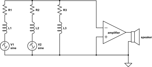
To explain how the signals are mixed when the pickups are in parallel I will use this schematic representation:

schematic

simulate this circuit – Schematic created using CircuitLab

I model the pickup element as a Voltage source (the EMF induced by playing the strings), some series inductance (you can ignore this) and some series resistance.

The voltage / current produced by V1 will divide itself across all other elements in the circuit. The same is true for V2. Electrical engineers learn how to do the calculations on this in their first year (I did and I hope that's still true). For this calculation you can determine the resulting voltages of V1 and V2 individually and then later add them up.

What the resulting voltage going into the amplifier will be does not matter much, fact is that the signals are simply added up and end up "everywhere" in the circuit.

Maybe the thing that you missed is that each pickup element has some series resistance, this makes then "play nice" when they are connected in parallel. In the power plant example I mentioned, these resistances are extremely low and that means the voltage sources don not "play nice" as currents can get out of hand.

\$\endgroup\$
4
  • \$\begingroup\$ But how do their signals combine in parallel? In series it makes sense because its like offsetting the ground of one using the voltage generated by another. In parallel i don't see how the signals mix together \$\endgroup\$
    – Taako
    Commented Sep 4, 2018 at 19:24
  • \$\begingroup\$ I will draw a schematic in my answer to explain that \$\endgroup\$ Commented Sep 4, 2018 at 19:48
  • \$\begingroup\$ i think i found a good diagram if you model the pickup as a voltages source in series with a resistor sub.allaboutcircuits.com/images/03040.png \$\endgroup\$
    – Taako
    Commented Sep 4, 2018 at 19:49
  • \$\begingroup\$ Indeed, that shows how it works, it is similar to my schematic (if you ignore my inductors). \$\endgroup\$ Commented Sep 4, 2018 at 20:00
1
\$\begingroup\$

What i don't understand is when they are in parallel, if each generates a different voltage and they are shorted together how does that not cause massive current problems.

A little bit of preamble: -

A single guitar pickup is equivalent to a small voltage source in series with a large inductance. This is why you would use a high impedance input circuit when amplifying a guitar pick-up because, if the input impedance was low you would get a regular performance from bass to mid but a substantially weakened performance at treble.

In other words, a pickup has a substantial impedance built into the the device and this means you can add two pick-up signals by passive mixing. If the two pick-ups are similar then there won't be any unexpected roll-off of high frequencies byt you'll still need a high input impedance amplifier for the combined signal.

It works exactly the same as combining two parallel voltage sources each with a series resistor and taking the summing junction as the output.

\$\endgroup\$
4
  • \$\begingroup\$ so it's modeled similarly to this circuit: sub.allaboutcircuits.com/images/03040.png correct? \$\endgroup\$
    – Taako
    Commented Sep 4, 2018 at 19:31
  • \$\begingroup\$ @Taako yes that is how the voltages sum plus the other benefit is that the shield or screen on the pickup that might be wired in series can still be ground referenced and thus produce a quieter solution in many cases. \$\endgroup\$
    – Andy aka
    Commented Sep 4, 2018 at 19:35
  • \$\begingroup\$ this also explains why people say series pickup configuration is louder than parallel. Since in parallel its mixing the signals with an averager instead of just adding them together (series). Thanks! \$\endgroup\$
    – Taako
    Commented Sep 4, 2018 at 19:46
  • \$\begingroup\$ Another note, since the pickups are physically some distance apart from each other, the vibrating nodes do not reach both at exactly the same time. So it is possible to wire two pickups in anti-parallel, and achieve "hum-bucking" without complete signal loss. \$\endgroup\$
    – rdtsc
    Commented Sep 4, 2018 at 20:14
0
\$\begingroup\$

A humbucker pickup can have an inductance of 3 to 4.5 Henries. Also the DC resistance can be anything between 5 to 10 kOhms.

Besides, passive humbuckers can generate only 1.5Vrms even with a 3-string strong power chord.

It can't be any current- or energy/power-related problems with that low-level voltages and high inductances. Also please note that you are paralleling two different voltage sources with "high output impedances".

\$\endgroup\$

Your Answer

By clicking “Post Your Answer”, you agree to our terms of service and acknowledge you have read our privacy policy.

Not the answer you're looking for? Browse other questions tagged or ask your own question.