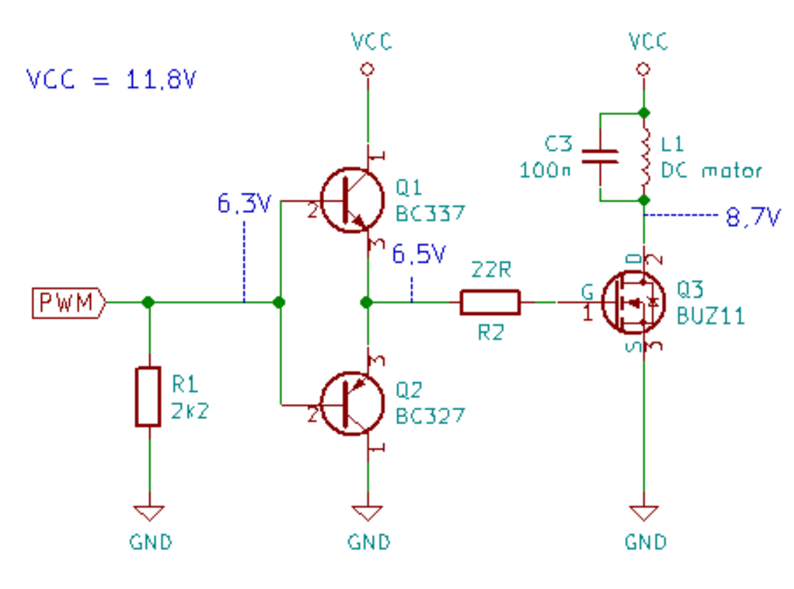
In some books and articles they say that to protect the MOSFET from overheating when working in PWM mode two BJT transistors are used as in the image, others recommend the use of a driver for MOSFETs such as MCP 1404. What is the difference between using one or another?

-
1\$\begingroup\$ BJT may seem like a simple solution... but simulate it. The "devil" is in the details. \$\endgroup\$– rdtscCommented Dec 4, 2020 at 14:37
-
\$\begingroup\$ The image shown is called as totem-pole MOSFET driver , actual name is different. Whether to use Totem-pole driver or MOSFET driver IC depends on PWM frequency, Actual MOSFET to be driven. Normally MOSFET IC drivers will have strong & controlled drive & Protections will be integrated. It's left to designer to choose. \$\endgroup\$– user19579Commented Dec 4, 2020 at 15:13
-
1\$\begingroup\$ Missing free-wheeling diode! \$\endgroup\$– winnyCommented Dec 4, 2020 at 15:19
-
\$\begingroup\$ Yeah, you need a snubber diode across the motor. \$\endgroup\$– ReinderienCommented Dec 4, 2020 at 16:17
-
\$\begingroup\$ snubber diode between the motor or between the Drain-Source? and what V-W would be for the zener? \$\endgroup\$– Ricardo CasimiroCommented Dec 4, 2020 at 16:54
3 Answers
Both will work. The objective is to drive the gate hard to switch the transistor quickly between it's on state and off state. This means it spends very little time in the 'half on' linear region where it will be dissipating power.
The output stage of an integrated driver will look very like the discrete solution that you showed, however they will include extra functionality like over current protection, enable or inverting/non-inverting option. A Schmitt trigger input may also be included for noise protection.
That pair of transistors is a driver stage, and because it is so simple it has a number of drawbacks. Because it requires multiple packages it's more expensive to do the PCB assembly than a driver. If you did overcome the drawbacks, through man-hours spent designing a driver, then it would have more components and be even more expensive to manufacture, not to mention less reliable simply by the weight of the additional solder joints.
At some point, for each product design, the costs associated with the extra time and trouble associated with a home-rolled driver stage exceeds the cost of a driver chip -- then you use a driver chip.
The driver is tailored for MOSFET/IGBT gate driving, it has also some protection like UVLO,..it may also ensure that gate is low (and not floating) in absence of Vcc.
