0
\$\begingroup\$

I want to build the cricuit like on the image below: Circuit Image
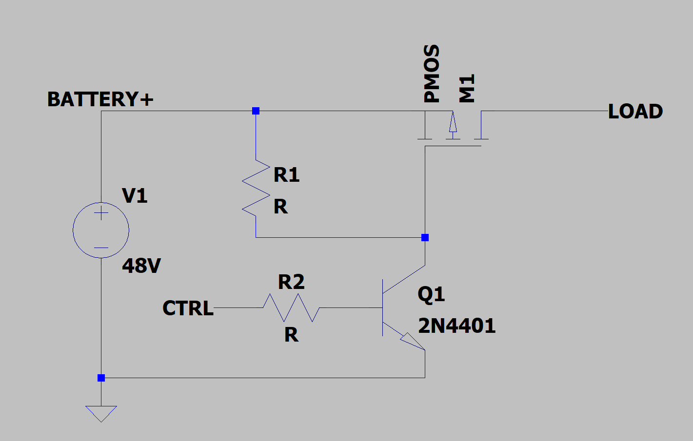
  • V1 - Is a 14S LiPo battery(there would be fuse in real life between positive battery terminal and "BATTERY+"
  • M1 - PMOS acting as a load switch
  • LOAD - Place where the load should be(DC Motor controller)
  • CTRL - pin turning the LOAD on/off

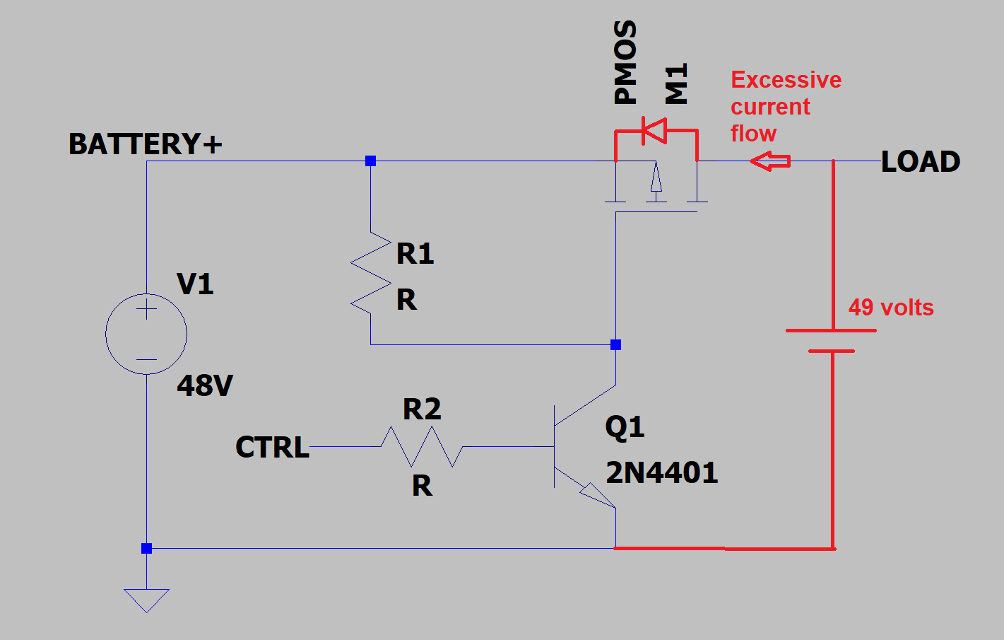
Q. What would happen if by mistake higher voltage than the battery would be connected where the LOAD is? I assume M1 Body diode would conduct causing overheating and potentialy burn the M1.

\$\endgroup\$
2
  • \$\begingroup\$ And the other problem is that your PMOS needs a VGSmax of -48V \$\endgroup\$
    – RoyC
    Commented Dec 16, 2020 at 19:20
  • \$\begingroup\$ Sure, the Zener diode should be placed! \$\endgroup\$
    – Bip
    Commented Dec 17, 2020 at 11:11

1 Answer 1

4
\$\begingroup\$

I assume M1 Body diode would conduct causing overheating and potentially burn the M1

enter image description here

Yes it could.

\$\endgroup\$
0

Your Answer

By clicking “Post Your Answer”, you agree to our terms of service and acknowledge you have read our privacy policy.

Not the answer you're looking for? Browse other questions tagged or ask your own question.