I'm currently redesigning a board that has a high failure rate. The design consist of three power rails 3.3v 12v and 24v
- 3.3v is coming from an USB powered Nucleo STM dev board
- 24v is my input power from a DIN rail PSU and is distributed via a copper plane on the entire board.
- 12v is generated with a LDO from the 24v rail.
- GND is all interconnected with a copper ground plane.
The board has six Geckodrive stepperdrives mounted on it, those are definitely causing the failures.
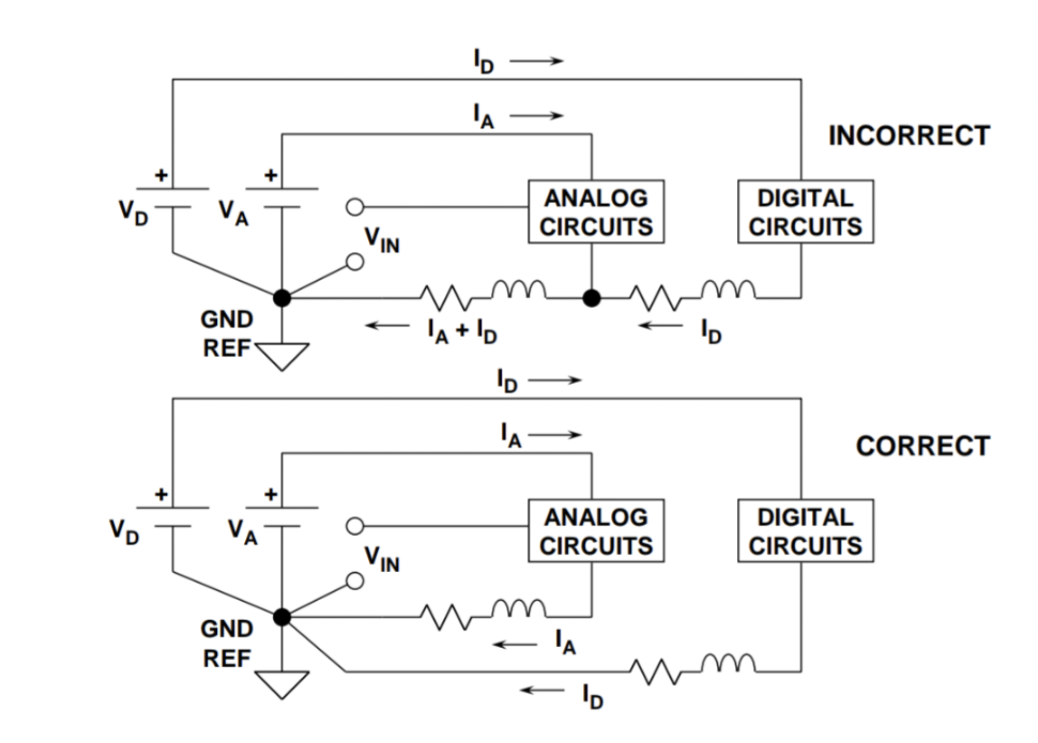
Geckodrives have two ground pins, one for logic and one for powering the steppermotors. They say I should first of all route the 24v as a track to each Geckodrive instead of using a 24V powerplane. (star network) And also never interconnect the two ground inputs.
So what I was planning to do is giving all 3.3v & 12v devices + Geckodrive logic ground the ground of my Nucleo board. And the Geckodrive power grounds are connected to my 24v PSU ground.
But how to split the ground at the LDO? It has only one GND pin. If I give it PGND do my 12v powered device perform perfectly by having the GND of Nucleo board?
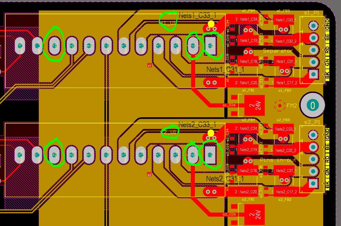
I'm only allowed to share a snippet of the PCB design that shows how the Geckodrives are interconnected.

At the left you have the logic GND of the Geckodrive. At the right the Power GND. Both grounds are connected to same GND plane The brown polygon is the 24V for all six Geckodrives to my surprise it barely makes a connection to the desired Geckodrive pin!!
So in this design all grounds are interconnected. And one big 24V polygon is feeding all six Geckodrives (so far from star formation)

 Source: