0
\$\begingroup\$

I have to design an LED driver for work. I am using the IS31LT3360 as the driver chip. On page 10 of its datasheet it states the chip can be driven with pwm. I came up with the following circuit. I would appriciate any feedback on wether I am doing this correctly. The mosfet is driven with a 0-3.3V PWM signal.

I am a little confused about this line on the datasheet:

"The PWM signal must have the driving ability to drive internal 500kΩ pull-up resistor. "

What does that mean? I am not sure what driving a resistor means.

Datasheet IS31LT3360 :

http://www.issi.com/WW/pdf/31LT3360.pdf enter image description here
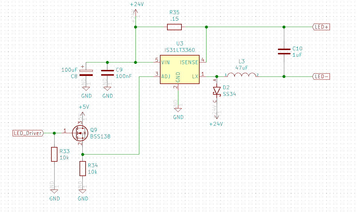
Edit after Marcus's comment. The datasheet suggests using a MCUs output (AS LONG AS IT IS BELOW 5V AND ABOVE 1.2V, better?) as below to drive the chip.

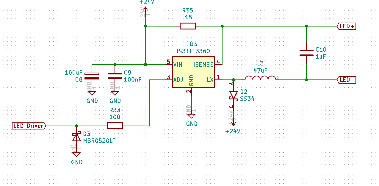
enter image description here

\$\endgroup\$
11
  • 1
    \$\begingroup\$ Ok, I feel like I should write the following: couple of days ago, you were in the middle of design for your bachelor thesis, now you're deigning a LED driver for work. Especially if you're doing your bachelor thesis within a company (as opposed to at a university institute), make triple sure that you get enough time to finish your thesis. Talk to your boss about that. Calculate how many hours working on your bachelor's is supposed to take, and make 100% sure you get that time, and the company is on-board with that. I've seen industry bachelor theses fail due to the student working too much. \$\endgroup\$ Commented Jan 13, 2021 at 17:05
  • \$\begingroup\$ @MarcusMüller I am working for an Institute. My bach. thesis is interconnected. This LED driver will go into the same system as my bach. thesis. Boss wants the machine to look prettier \$\endgroup\$
    – Emre Mutlu
    Commented Jan 13, 2021 at 17:10
  • \$\begingroup\$ You are working on your bachelor thesis? Please break your question down...tell us exactly which part of the sentence you don't understand. Do you know what "pull-up" is? \$\endgroup\$ Commented Jan 13, 2021 at 17:17
  • \$\begingroup\$ @ElliotAlderson I know what a pull up is. I am not sure what driving a resistor means thoguh. \$\endgroup\$
    – Emre Mutlu
    Commented Jan 13, 2021 at 17:18
  • 1
    \$\begingroup\$ @EmreMUTLU no, it doesn't. The next sentence says the high-going threshold is 1.2 V. So, your 3.3 V is totally sufficient. ("many other designs" doesn't matter – what matters is your design in your application, and my guess is that if your B.Sc. is about circuit design, then that's twice as true!) Instead, the datasheet actually suggests directly driving the ADJ pin from a microcontroller pin with naught but a series resistor (and a protection diode). \$\endgroup\$ Commented Jan 13, 2021 at 17:33

1 Answer 1

2
\$\begingroup\$

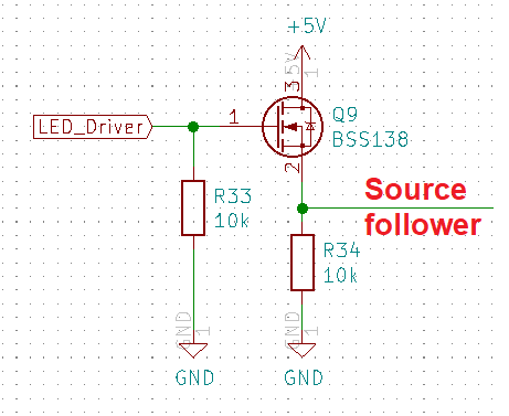
The main problem is that you haven't designed a level translator: -

enter image description here

It's a source follower and the voltage at the source will be approximately what is at the gate but about a volt lower in amplitude (MOSFET depending). It won't give a 5 volt PWM level translation. To do that you need the source connected to ground and a resistor from drain to 5 volts. This will produce what you need but, bear in mind it is an inverting stage so, 3.3 volts in produces 0 volts out and 0 volts in produces 5 volts out.

The PWM signal must have the driving ability to drive internal 500kΩ pull-up resistor. What does that mean?

It means that when you have correctly re-wired your MOSFET as per the above, the loading resistance of the ADJ input is 500 kΩ but, given that it is a pull-up internal resistance, it's of little consequence given that the "to-be-added" drain pull up resistor (as per my earlier words) you would choose (about 10 kΩ) would swamp it.

\$\endgroup\$

Your Answer

By clicking “Post Your Answer”, you agree to our terms of service and acknowledge you have read our privacy policy.

Not the answer you're looking for? Browse other questions tagged or ask your own question.