I'm trying to simulate a model of a 3-phase transformer in LTspice.
My first attempt with different K values worked, but it didn't include the core saturation.
Now I tried to built a new model with the help of the example from analog spiceman in the LTspice group.
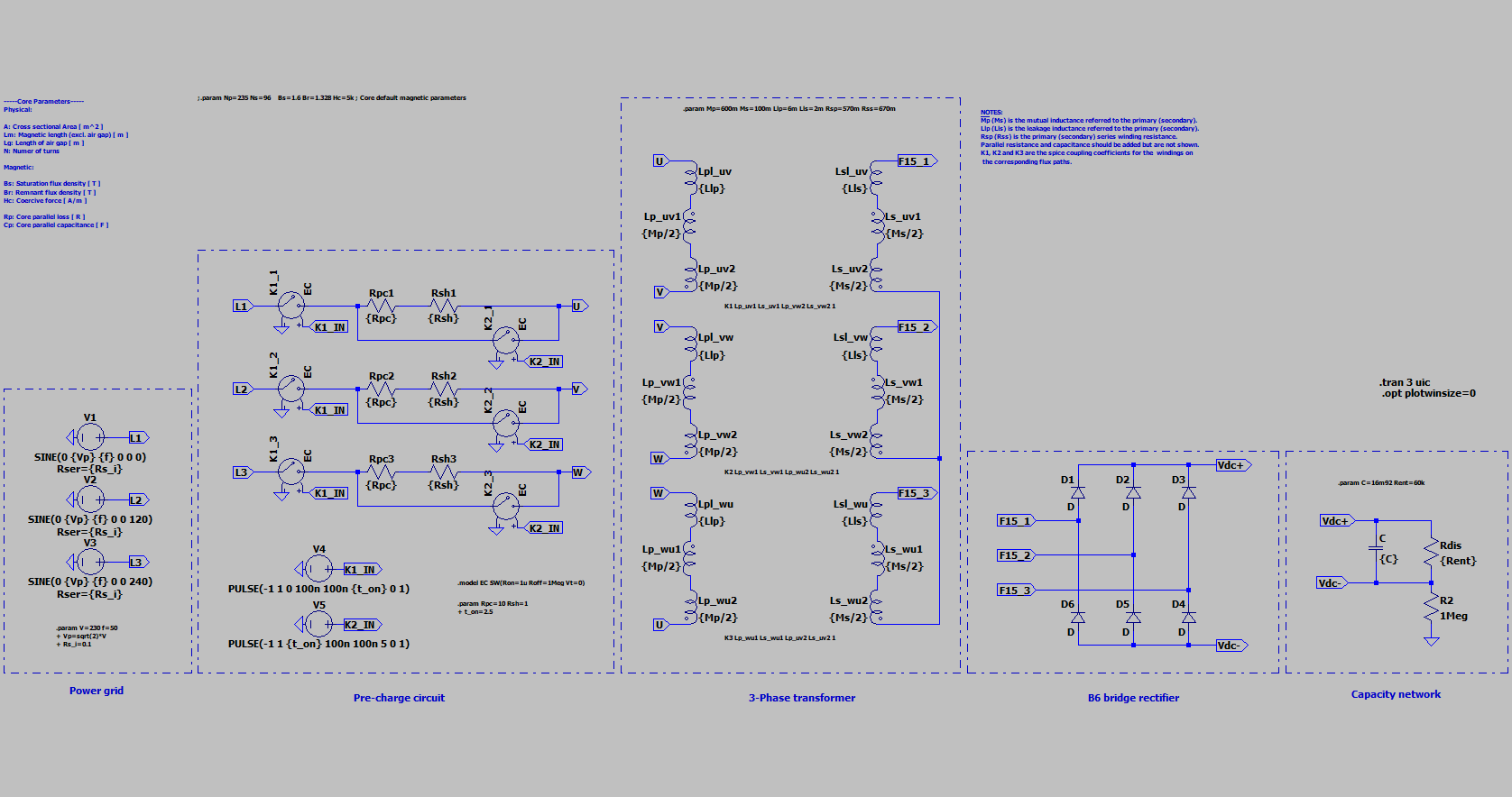
The problem with my model is that it has 3 primary windings and 18 secondary windings on a E-core. The primary is connected in delta and the secondary are connected in star. Also it has B6 bridge rectifier on the secondary side with a high capacity bank.
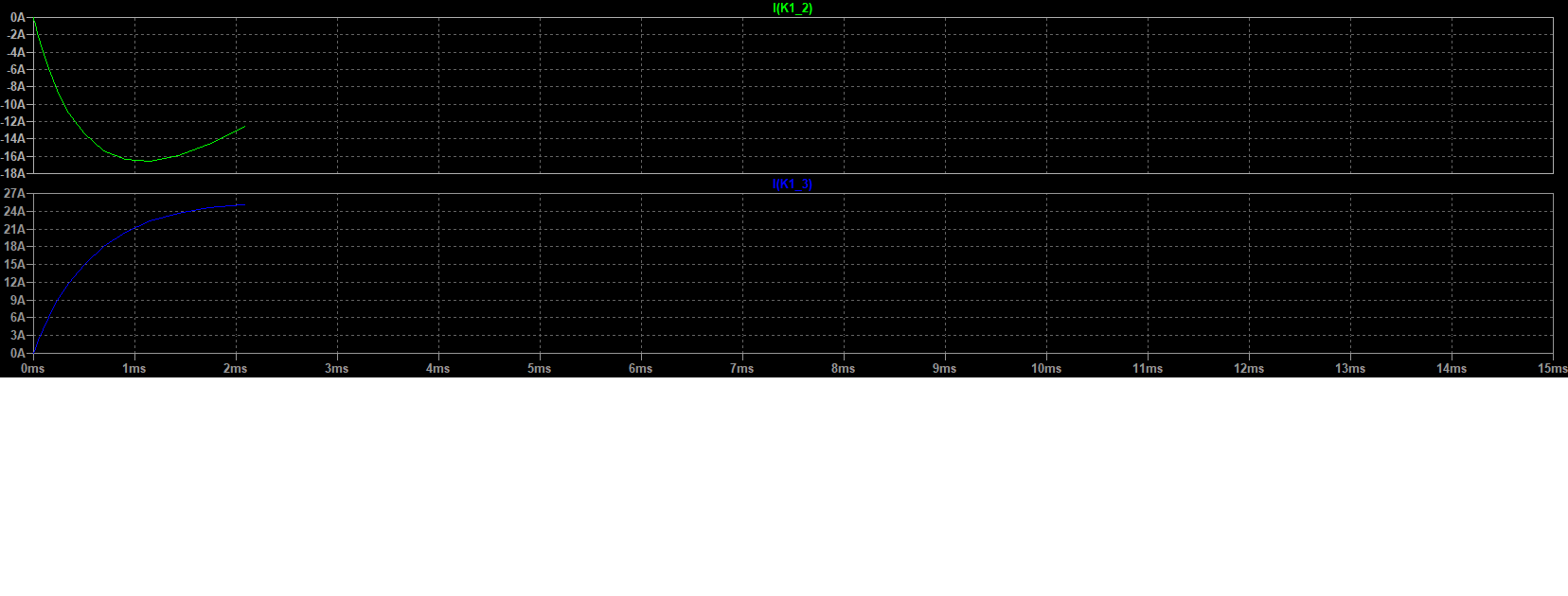
For the first attempt of the new model, I tried to make it simple. That's why I put all the secondary windings for each transformer leg together. My problem now is that the simulation runs through, but the plot only shows some ms of the simulation in .trans
Maybe someone has got a tip for me?
To compare it to reality I got some meassured values on the primary side:
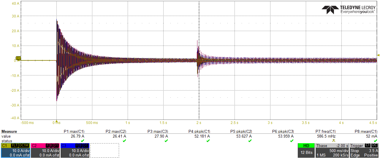 First peak is start-up with resistor. Second peak is switched to power grid.
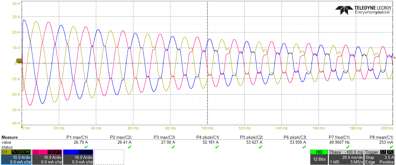 Starting process with the start-up resistors.
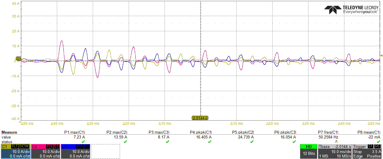 Switching from precharge resistors to power grid.
Here is the code of the simpler "working" simulation:
Version 4
SHEET 1 3692 1008
WIRE 1488 -272 1440 -272
WIRE 1968 -272 1920 -272
WIRE 1488 -160 1488 -192
WIRE 1488 -160 1440 -160
WIRE 1920 -160 1920 -192
WIRE 1920 -160 1808 -160
WIRE 1488 -96 1440 -96
WIRE 1968 -96 1920 -96
WIRE 1488 16 1488 -16
WIRE 1488 16 1440 16
WIRE 1808 16 1808 -160
WIRE 1920 16 1920 -16
WIRE 1920 16 1808 16
WIRE 512 64 480 64
WIRE 528 64 512 64
WIRE 736 64 608 64
WIRE 880 64 816 64
WIRE 1184 64 960 64
WIRE 1216 64 1184 64
WIRE 1488 64 1440 64
WIRE 1968 64 1920 64
WIRE 608 112 592 112
WIRE 512 144 512 64
WIRE 1024 144 512 144
WIRE 1184 144 1184 64
WIRE 1184 144 1104 144
WIRE 1488 176 1488 144
WIRE 1488 176 1440 176
WIRE 1808 176 1808 16
WIRE 1920 176 1920 144
WIRE 1920 176 1808 176
WIRE 1104 192 1088 192
WIRE 512 256 480 256
WIRE 528 256 512 256
WIRE 736 256 608 256
WIRE 880 256 816 256
WIRE 1184 256 960 256
WIRE 1216 256 1184 256
WIRE 608 304 592 304
WIRE 512 336 512 256
WIRE 1024 336 512 336
WIRE 1184 336 1184 256
WIRE 1184 336 1104 336
WIRE 192 368 144 368
WIRE 1104 384 1088 384
WIRE 2512 432 2384 432
WIRE 2640 432 2512 432
WIRE 2704 432 2640 432
WIRE 512 448 480 448
WIRE 528 448 512 448
WIRE 736 448 608 448
WIRE 880 448 816 448
WIRE 1184 448 960 448
WIRE 1216 448 1184 448
WIRE 2384 464 2384 432
WIRE 2512 464 2512 432
WIRE 2640 464 2640 432
WIRE 608 496 592 496
WIRE 192 512 144 512
WIRE 512 528 512 448
WIRE 1024 528 512 528
WIRE 1184 528 1184 448
WIRE 1184 528 1104 528
WIRE 2384 560 2384 528
WIRE 2384 560 2288 560
WIRE 3072 560 3024 560
WIRE 3200 560 3072 560
WIRE 1104 576 1088 576
WIRE 3072 592 3072 560
WIRE 3200 592 3200 560
WIRE 2512 640 2512 528
WIRE 2512 640 2288 640
WIRE 192 656 144 656
WIRE 688 672 672 672
WIRE 3072 704 3072 656
WIRE 3072 704 3008 704
WIRE 3200 704 3200 672
WIRE 3200 704 3072 704
WIRE 2640 720 2640 528
WIRE 2640 720 2288 720
WIRE 3200 720 3200 704
WIRE 2384 752 2384 560
WIRE 2512 752 2512 640
WIRE 2640 752 2640 720
WIRE 688 800 672 800
WIRE 3200 832 3200 800
WIRE 2384 848 2384 816
WIRE 2512 848 2512 816
WIRE 2512 848 2384 848
WIRE 2640 848 2640 816
WIRE 2640 848 2512 848
WIRE 2704 848 2640 848
FLAG 64 368 0
FLAG 64 512 0
FLAG 64 656 0
FLAG 192 368 L1
IOPIN 192 368 Out
FLAG 192 512 L2
IOPIN 192 512 Out
FLAG 192 656 L3
IOPIN 192 656 Out
FLAG 544 112 0
FLAG 544 304 0
FLAG 544 496 0
FLAG 592 672 0
FLAG 688 672 K1_IN
IOPIN 688 672 Out
FLAG 608 496 K1_IN
IOPIN 608 496 In
FLAG 608 304 K1_IN
IOPIN 608 304 In
FLAG 608 112 K1_IN
IOPIN 608 112 In
FLAG 480 64 L1
IOPIN 480 64 In
FLAG 480 256 L2
IOPIN 480 256 In
FLAG 480 448 L3
IOPIN 480 448 In
FLAG 592 800 0
FLAG 688 800 K2_IN
IOPIN 688 800 Out
FLAG 1040 384 0
FLAG 1040 192 0
FLAG 1040 576 0
FLAG 1104 192 K2_IN
IOPIN 1104 192 In
FLAG 1104 384 K2_IN
IOPIN 1104 384 In
FLAG 1104 576 K2_IN
IOPIN 1104 576 In
FLAG 1216 64 U
IOPIN 1216 64 Out
FLAG 1216 256 V
IOPIN 1216 256 Out
FLAG 1216 448 W
IOPIN 1216 448 Out
FLAG 1440 -272 U
IOPIN 1440 -272 In
FLAG 1440 -160 V
IOPIN 1440 -160 In
FLAG 1440 -96 V
IOPIN 1440 -96 In
FLAG 1440 16 W
IOPIN 1440 16 In
FLAG 1440 64 W
IOPIN 1440 64 In
FLAG 1440 176 U
IOPIN 1440 176 In
FLAG 1968 -272 F15_1
IOPIN 1968 -272 Out
FLAG 1968 -96 F15_2
IOPIN 1968 -96 Out
FLAG 1968 64 F15_3
IOPIN 1968 64 Out
FLAG 2288 560 F15_1
IOPIN 2288 560 In
FLAG 2288 640 F15_2
IOPIN 2288 640 In
FLAG 2288 720 F15_3
IOPIN 2288 720 In
FLAG 2704 432 Vdc+
IOPIN 2704 432 Out
FLAG 2704 848 Vdc-
IOPIN 2704 848 Out
FLAG 3024 560 Vdc+
IOPIN 3024 560 In
FLAG 3008 704 Vdc-
IOPIN 3008 704 In
FLAG 3200 832 0
SYMBOL voltage 160 368 R90
WINDOW 0 -32 56 VBottom 2
WINDOW 3 32 56 VTop 2
WINDOW 39 60 56 VTop 2
WINDOW 123 0 0 Left 0
SYMATTR InstName V1
SYMATTR Value SINE(0 {Vp} {f} 0 0 0)
SYMATTR SpiceLine Rser={Rs_i}
SYMBOL voltage 160 512 R90
WINDOW 0 -32 56 VBottom 2
WINDOW 3 32 56 VTop 2
WINDOW 123 0 0 Left 0
WINDOW 39 60 56 VTop 2
SYMATTR InstName V2
SYMATTR Value SINE(0 {Vp} {f} 0 0 120)
SYMATTR SpiceLine Rser={Rs_i}
SYMBOL voltage 160 656 R90
WINDOW 0 -32 56 VBottom 2
WINDOW 3 32 56 VTop 2
WINDOW 123 0 0 Left 0
WINDOW 39 60 56 VTop 2
SYMATTR InstName V3
SYMATTR Value SINE(0 {Vp} {f} 0 0 240)
SYMATTR SpiceLine Rser={Rs_i}
SYMBOL sw 512 64 R270
SYMATTR InstName K1_1
SYMATTR Value EC
SYMBOL sw 512 256 R270
SYMATTR InstName K1_2
SYMATTR Value EC
SYMBOL sw 512 448 R270
SYMATTR InstName K1_3
SYMATTR Value EC
SYMBOL voltage 688 672 R90
WINDOW 0 -32 56 VBottom 2
WINDOW 3 32 56 VTop 2
WINDOW 123 0 0 Left 0
WINDOW 39 0 0 Left 0
SYMATTR InstName V4
SYMATTR Value PULSE(-1 1 0 100n 100n {t_on} 0 1)
SYMBOL res 832 48 R90
WINDOW 0 0 56 VBottom 2
WINDOW 3 32 56 VTop 2
SYMATTR InstName Rpc1
SYMATTR Value {Rpc}
SYMBOL res 976 48 R90
WINDOW 0 0 56 VBottom 2
WINDOW 3 32 56 VTop 2
SYMATTR InstName Rsh1
SYMATTR Value {Rsh}
SYMBOL res 832 240 R90
WINDOW 0 0 56 VBottom 2
WINDOW 3 32 56 VTop 2
SYMATTR InstName Rpc2
SYMATTR Value {Rpc}
SYMBOL voltage 688 800 R90
WINDOW 0 -32 56 VBottom 2
WINDOW 3 32 56 VTop 2
WINDOW 123 0 0 Left 0
WINDOW 39 0 0 Left 0
SYMATTR InstName V5
SYMATTR Value PULSE(-1 1 {t_on} 100n 100n 5 0 1)
SYMBOL res 832 432 R90
WINDOW 0 0 56 VBottom 2
WINDOW 3 32 56 VTop 2
SYMATTR InstName Rpc3
SYMATTR Value {Rpc}
SYMBOL res 976 240 R90
WINDOW 0 0 56 VBottom 2
WINDOW 3 32 56 VTop 2
SYMATTR InstName Rsh2
SYMATTR Value {Rsh}
SYMBOL res 976 432 R90
WINDOW 0 0 56 VBottom 2
WINDOW 3 32 56 VTop 2
SYMATTR InstName Rsh3
SYMATTR Value {Rsh}
SYMBOL sw 1008 144 R270
SYMATTR InstName K2_1
SYMATTR Value EC
SYMBOL sw 1008 336 R270
SYMATTR InstName K2_2
SYMATTR Value EC
SYMBOL sw 1008 528 R270
SYMATTR InstName K2_3
SYMATTR Value EC
SYMBOL ind2 1472 -288 R0
SYMATTR InstName Lp_uv
SYMATTR Value {Lp_uv}
SYMATTR SpiceLine Rser={Rlp}
SYMATTR Type ind
SYMBOL ind2 1472 -112 R0
SYMATTR InstName Lp_vw
SYMATTR Value {Lp_vw}
SYMATTR Type ind
SYMATTR SpiceLine Rser={Rlp}
SYMBOL ind2 1472 48 R0
SYMATTR InstName Lp_wu
SYMATTR Value {Lp_wu}
SYMATTR SpiceLine Rser={Rlp}
SYMATTR Type ind
SYMBOL ind2 1936 -288 M0
SYMATTR InstName Ls_uv
SYMATTR Value {Ls_uv}
SYMATTR SpiceLine Rser={Rls}
SYMATTR Type ind
SYMBOL ind2 1936 -112 M0
SYMATTR InstName Ls_vw
SYMATTR Value {Ls_vw}
SYMATTR SpiceLine Rser={Rls}
SYMATTR Type ind
SYMBOL ind2 1936 48 M0
SYMATTR InstName Ls_wu
SYMATTR Value {Ls_wu}
SYMATTR SpiceLine Rser={Rls}
SYMATTR Type ind
SYMBOL diode 2400 528 R180
WINDOW 0 24 64 Left 2
WINDOW 3 24 0 Left 2
SYMATTR InstName D1
SYMBOL diode 2528 528 R180
WINDOW 0 24 64 Left 2
WINDOW 3 24 0 Left 2
SYMATTR InstName D2
SYMBOL diode 2656 528 R180
WINDOW 0 24 64 Left 2
WINDOW 3 24 0 Left 2
SYMATTR InstName D3
SYMBOL diode 2656 816 R180
WINDOW 0 24 64 Left 2
WINDOW 3 24 0 Left 2
SYMATTR InstName D4
SYMBOL diode 2528 816 R180
WINDOW 0 24 64 Left 2
WINDOW 3 24 0 Left 2
SYMATTR InstName D5
SYMBOL diode 2400 816 R180
WINDOW 0 24 64 Left 2
WINDOW 3 24 0 Left 2
SYMATTR InstName D6
SYMBOL cap 3056 592 R0
SYMATTR InstName C
SYMATTR Value {C}
SYMBOL res 3184 576 R0
SYMATTR InstName Rdis
SYMATTR Value {Rent}
SYMBOL res 3184 704 R0
SYMATTR InstName R2
SYMATTR Value 1Meg
TEXT -96 -408 Left 1 ;-----Core Parameters-----\nPhysical:\n \nA: Cross sectional Area [ m^2 ]\nLm: Magnetic length (excl. air gap) [ m ]\nLg: Length of air gap [ m ]\nN: Numer of turns\n \nMagnetic:\n \nBs: Saturation flux density [ T ]\nBr: Remnant flux density [ T ]\nHc: Coercive force [ A/m ]\n \nRp: Core parallel loss [ R ]\nCp: Core parallel capacitance [ F ]
TEXT 352 -416 Left 1 ;.param Np=235 Ns=96    Bs=1.6 Br=1.328 Hc=5k ; Core default magnetic parameters
TEXT 24 808 Left 1 !.param V=230 f=50\n+ Vp=sqrt(2)*V\n+ Rs_i=0.1
TEXT 952 704 Left 1 !.model EC SW(Ron=1u Roff=1Meg Vt=0)
TEXT 1472 -392 Left 1 ;.param Mp=600m Ms=100m Llp=6m Lls=2m Rsp=570m Rss=670m
TEXT 56 952 Left 2 ;Power grid
TEXT 712 968 Left 2 ;Pre-charge circuit
TEXT 1624 968 Left 2 ;3-Phase transformer
TEXT 2160 -384 Left 1 ;NOTES:\n_Mp (Ms) is the mutual inductance referred to the primary (secondary).\nLlp (Lls) is the leakage inductance referred to the primary (secondary).\nRsp (Rss) is the primary (secondary) series winding resistance.\nParallel resistance and capacitance should be added but are not shown.\nK1, K2 and K3 are the spice coupling coefficients for the  windings on\n the corresponding flux paths.
TEXT 3080 240 Left 2 !.tran 3 uic
TEXT 2984 472 Left 1 !.param C=16m92 Rent=60k
TEXT 952 752 Left 1 !.param Rpc=10 Rsh=1  t_on=2.0
TEXT 2408 968 Left 2 ;B6 bridge rectifier
TEXT 3016 960 Left 2 ;Capacity network
TEXT 3088 264 Left 2 !.opt plotwinsize=0
TEXT 1472 -368 Left 1 !.param Lp_uv=604m8 Lp_vw=695m5 Lp_wu=521m6\n+ Ls_uv=Lp_uv/5.99 Ls_vw=Lp_vw/5.99 Ls_wu=Lp_wu/5.99 \n+ Rlp=570m Rls=670m
TEXT 1632 232 Left 1 !K1 Lp_uv Ls_uv 0.999\nK2 Lp_uv Ls_vw -0.499\nK3 Lp_uv Ls_wu -0.499\nK4 Lp_uv Lp_vw -0.499\nK5 Lp_uv Lp_wu -0.499\nK6 Lp_vw Ls_vw 0.999\nK7 Lp_vw Ls_uv -0.499\nK8 Lp_vw Lp_wu -0.499\nK9 Lp_vw Ls_wu -0.499\nK10 Lp_wu Ls_wu 0.999\nK11 Lp_wu Ls_vw -0.499\nK12 Lp_wu Ls_uv -0.499\nK13 Ls_uv Ls_vw -0.499\nK14 Ls_uv Ls_wu -0.499\nK15 Ls_vw Ls_wu -0.499
RECTANGLE Normal 336 912 -96 256 3
RECTANGLE Normal 1312 912 352 -64 3
RECTANGLE Normal 2112 912 1328 -416 3
RECTANGLE Normal 2848 912 2128 400 3
RECTANGLE Normal 3376 912 2864 400 3
Here is copy of the .asc file:
Version 4
SHEET 1 3692 1008
WIRE 1488 -272 1440 -272
WIRE 1968 -272 1920 -272
WIRE 1488 -160 1488 -192
WIRE 1920 -160 1920 -192
WIRE 1488 -48 1488 -80
WIRE 1920 -48 1920 -80
WIRE 1488 32 1440 32
WIRE 2064 32 1920 32
WIRE 496 64 480 64
WIRE 528 64 496 64
WIRE 736 64 608 64
WIRE 880 64 816 64
WIRE 1184 64 960 64
WIRE 1216 64 1184 64
WIRE 608 112 592 112
WIRE 1488 112 1440 112
WIRE 1968 112 1920 112
WIRE 496 144 496 64
WIRE 1024 144 496 144
WIRE 1184 144 1184 64
WIRE 1184 144 1104 144
WIRE 1104 192 1088 192
WIRE 1488 224 1488 192
WIRE 1920 224 1920 192
WIRE 496 256 480 256
WIRE 528 256 496 256
WIRE 736 256 608 256
WIRE 880 256 816 256
WIRE 1184 256 960 256
WIRE 1216 256 1184 256
WIRE 608 304 592 304
WIRE 496 336 496 256
WIRE 1024 336 496 336
WIRE 1184 336 1184 256
WIRE 1184 336 1104 336
WIRE 1488 336 1488 304
WIRE 1920 336 1920 304
WIRE 192 368 144 368
WIRE 1104 384 1088 384
WIRE 1488 416 1440 416
WIRE 2064 416 2064 32
WIRE 2064 416 1920 416
WIRE 2512 432 2384 432
WIRE 2640 432 2512 432
WIRE 2704 432 2640 432
WIRE 496 448 480 448
WIRE 528 448 496 448
WIRE 736 448 608 448
WIRE 880 448 816 448
WIRE 1184 448 960 448
WIRE 1216 448 1184 448
WIRE 2384 464 2384 432
WIRE 2512 464 2512 432
WIRE 2640 464 2640 432
WIRE 608 496 592 496
WIRE 1488 496 1440 496
WIRE 1968 496 1920 496
WIRE 192 512 144 512
WIRE 496 528 496 448
WIRE 1024 528 496 528
WIRE 1184 528 1184 448
WIRE 1184 528 1104 528
WIRE 2384 560 2384 528
WIRE 2384 560 2288 560
WIRE 3072 560 3024 560
WIRE 3200 560 3072 560
WIRE 1104 576 1088 576
WIRE 3072 592 3072 560
WIRE 3200 592 3200 560
WIRE 1488 608 1488 576
WIRE 1920 608 1920 576
WIRE 2512 640 2512 528
WIRE 2512 640 2288 640
WIRE 192 656 144 656
WIRE 688 672 672 672
WIRE 3072 704 3072 656
WIRE 3072 704 3008 704
WIRE 3200 704 3200 672
WIRE 3200 704 3072 704
WIRE 1488 720 1488 688
WIRE 1920 720 1920 688
WIRE 2640 720 2640 528
WIRE 2640 720 2288 720
WIRE 3200 720 3200 704
WIRE 2384 752 2384 560
WIRE 2512 752 2512 640
WIRE 2640 752 2640 720
WIRE 688 800 672 800
WIRE 1488 800 1440 800
WIRE 2064 800 2064 416
WIRE 2064 800 1920 800
WIRE 3200 832 3200 800
WIRE 2384 848 2384 816
WIRE 2512 848 2512 816
WIRE 2512 848 2384 848
WIRE 2640 848 2640 816
WIRE 2640 848 2512 848
WIRE 2704 848 2640 848
FLAG 64 368 0
FLAG 64 512 0
FLAG 64 656 0
FLAG 192 368 L1
IOPIN 192 368 Out
FLAG 192 512 L2
IOPIN 192 512 Out
FLAG 192 656 L3
IOPIN 192 656 Out
FLAG 544 112 0
FLAG 544 304 0
FLAG 544 496 0
FLAG 592 672 0
FLAG 688 672 K1_IN
IOPIN 688 672 Out
FLAG 608 496 K1_IN
IOPIN 608 496 In
FLAG 608 304 K1_IN
IOPIN 608 304 In
FLAG 608 112 K1_IN
IOPIN 608 112 In
FLAG 480 64 L1
IOPIN 480 64 In
FLAG 480 256 L2
IOPIN 480 256 In
FLAG 480 448 L3
IOPIN 480 448 In
FLAG 592 800 0
FLAG 688 800 K2_IN
IOPIN 688 800 Out
FLAG 1040 384 0
FLAG 1040 192 0
FLAG 1040 576 0
FLAG 1104 192 K2_IN
IOPIN 1104 192 In
FLAG 1104 384 K2_IN
IOPIN 1104 384 In
FLAG 1104 576 K2_IN
IOPIN 1104 576 In
FLAG 1216 64 U
IOPIN 1216 64 Out
FLAG 1216 256 V
IOPIN 1216 256 Out
FLAG 1216 448 W
IOPIN 1216 448 Out
FLAG 1440 -272 U
IOPIN 1440 -272 In
FLAG 1440 32 V
IOPIN 1440 32 In
FLAG 1440 112 V
IOPIN 1440 112 In
FLAG 1440 416 W
IOPIN 1440 416 In
FLAG 1440 496 W
IOPIN 1440 496 In
FLAG 1440 800 U
IOPIN 1440 800 In
FLAG 1968 -272 F15_1
IOPIN 1968 -272 Out
FLAG 1968 112 F15_2
IOPIN 1968 112 Out
FLAG 1968 496 F15_3
IOPIN 1968 496 Out
FLAG 2288 560 F15_1
IOPIN 2288 560 In
FLAG 2288 640 F15_2
IOPIN 2288 640 In
FLAG 2288 720 F15_3
IOPIN 2288 720 In
FLAG 2704 432 Vdc+
IOPIN 2704 432 Out
FLAG 2704 848 Vdc-
IOPIN 2704 848 Out
FLAG 3024 560 Vdc+
IOPIN 3024 560 In
FLAG 3008 704 Vdc-
IOPIN 3008 704 In
FLAG 3200 832 0
SYMBOL voltage 160 368 R90
WINDOW 0 -32 56 VBottom 2
WINDOW 3 32 56 VTop 2
WINDOW 39 60 56 VTop 2
SYMATTR InstName V1
SYMATTR Value SINE(0 {Vp} {f} 0 0 0)
SYMATTR SpiceLine Rser={Rs_i}
SYMBOL voltage 160 512 R90
WINDOW 0 -32 56 VBottom 2
WINDOW 3 32 56 VTop 2
WINDOW 123 0 0 Left 0
WINDOW 39 60 56 VTop 2
SYMATTR InstName V2
SYMATTR Value SINE(0 {Vp} {f} 0 0 120)
SYMATTR SpiceLine Rser={Rs_i}
SYMBOL voltage 160 656 R90
WINDOW 0 -32 56 VBottom 2
WINDOW 3 32 56 VTop 2
WINDOW 123 0 0 Left 0
WINDOW 39 60 56 VTop 2
SYMATTR InstName V3
SYMATTR Value SINE(0 {Vp} {f} 0 0 240)
SYMATTR SpiceLine Rser={Rs_i}
SYMBOL sw 512 64 R270
SYMATTR InstName K1_1
SYMATTR Value EC
SYMBOL sw 512 256 R270
SYMATTR InstName K1_2
SYMATTR Value EC
SYMBOL sw 512 448 R270
SYMATTR InstName K1_3
SYMATTR Value EC
SYMBOL voltage 688 672 R90
WINDOW 0 -32 56 VBottom 2
WINDOW 3 32 56 VTop 2
WINDOW 123 0 0 Left 0
WINDOW 39 0 0 Left 0
SYMATTR InstName V4
SYMATTR Value PULSE(-1 1 0 100n 100n {t_on} 0 1)
SYMBOL res 832 48 R90
WINDOW 0 0 56 VBottom 2
WINDOW 3 32 56 VTop 2
SYMATTR InstName Rpc1
SYMATTR Value {Rpc}
SYMBOL res 976 48 R90
WINDOW 0 0 56 VBottom 2
WINDOW 3 32 56 VTop 2
SYMATTR InstName Rsh1
SYMATTR Value {Rsh}
SYMBOL res 832 240 R90
WINDOW 0 0 56 VBottom 2
WINDOW 3 32 56 VTop 2
SYMATTR InstName Rpc2
SYMATTR Value {Rpc}
SYMBOL voltage 688 800 R90
WINDOW 0 -32 56 VBottom 2
WINDOW 3 32 56 VTop 2
WINDOW 123 0 0 Left 0
WINDOW 39 0 0 Left 0
SYMATTR InstName V5
SYMATTR Value PULSE(-1 1 {t_on} 100n 100n 5 0 1)
SYMBOL res 832 432 R90
WINDOW 0 0 56 VBottom 2
WINDOW 3 32 56 VTop 2
SYMATTR InstName Rpc3
SYMATTR Value {Rpc}
SYMBOL res 976 240 R90
WINDOW 0 0 56 VBottom 2
WINDOW 3 32 56 VTop 2
SYMATTR InstName Rsh2
SYMATTR Value {Rsh}
SYMBOL res 976 432 R90
WINDOW 0 0 56 VBottom 2
WINDOW 3 32 56 VTop 2
SYMATTR InstName Rsh3
SYMATTR Value {Rsh}
SYMBOL sw 1008 144 R270
SYMATTR InstName K2_1
SYMATTR Value EC
SYMBOL sw 1008 336 R270
SYMATTR InstName K2_2
SYMATTR Value EC
SYMBOL sw 1008 528 R270
SYMATTR InstName K2_3
SYMATTR Value EC
SYMBOL ind 1472 -288 R0
SYMATTR InstName Lpl_uv
SYMATTR Value {Llp}
SYMATTR SpiceLine Rser={Rsp}
SYMBOL ind 1472 96 R0
SYMATTR InstName Lpl_vw
SYMATTR Value {Llp}
SYMATTR SpiceLine Rser={Rsp}
SYMBOL ind 1472 480 R0
SYMATTR InstName Lpl_wu
SYMATTR Value {Llp}
SYMATTR SpiceLine Rser={Rsp}
SYMBOL ind2 1504 -64 R180
WINDOW 0 36 80 Left 2
WINDOW 3 36 40 Left 2
SYMATTR InstName Lp_uv1
SYMATTR Value {Mp/2}
SYMATTR Type ind
SYMBOL ind2 1472 -64 R0
SYMATTR InstName Lp_uv2
SYMATTR Value {Mp/2}
SYMATTR Type ind
SYMBOL ind2 1504 320 R180
WINDOW 0 36 80 Left 2
WINDOW 3 36 40 Left 2
SYMATTR InstName Lp_vw1
SYMATTR Value {Mp/2}
SYMATTR Type ind
SYMBOL ind2 1472 320 R0
SYMATTR InstName Lp_vw2
SYMATTR Value {Mp/2}
SYMATTR Type ind
SYMBOL ind2 1504 704 R180
WINDOW 0 36 80 Left 2
WINDOW 3 36 40 Left 2
SYMATTR InstName Lp_wu1
SYMATTR Value {Mp/2}
SYMATTR Type ind
SYMBOL ind2 1472 704 R0
SYMATTR InstName Lp_wu2
SYMATTR Value {Mp/2}
SYMATTR Type ind
SYMBOL ind 1936 -288 M0
SYMATTR InstName Lsl_uv
SYMATTR Value {Lls}
SYMATTR SpiceLine Rser={Rss}
SYMBOL ind2 1904 -64 M180
WINDOW 0 36 80 Left 2
WINDOW 3 36 40 Left 2
SYMATTR InstName Ls_uv1
SYMATTR Value {Ms/2}
SYMATTR Type ind
SYMBOL ind2 1936 -64 M0
SYMATTR InstName Ls_uv2
SYMATTR Value {Ms/2}
SYMATTR Type ind
SYMBOL ind 1936 96 M0
SYMATTR InstName Lsl_vw
SYMATTR Value {Lls}
SYMATTR SpiceLine Rser={Rss}
SYMBOL ind2 1904 320 M180
WINDOW 0 36 80 Left 2
WINDOW 3 36 40 Left 2
SYMATTR InstName Ls_vw1
SYMATTR Value {Ms/2}
SYMATTR Type ind
SYMBOL ind2 1936 320 M0
SYMATTR InstName Ls_vw2
SYMATTR Value {Ms/2}
SYMATTR Type ind
SYMBOL ind 1936 480 M0
SYMATTR InstName Lsl_wu
SYMATTR Value {Lls}
SYMATTR SpiceLine Rser={Rss}
SYMBOL ind2 1904 704 M180
WINDOW 0 36 80 Left 2
WINDOW 3 36 40 Left 2
SYMATTR InstName Ls_wu1
SYMATTR Value {Ms/2}
SYMATTR Type ind
SYMBOL ind2 1936 704 M0
SYMATTR InstName Ls_wu2
SYMATTR Value {Ms/2}
SYMATTR Type ind
SYMBOL diode 2400 528 R180
WINDOW 0 24 64 Left 2
WINDOW 3 24 0 Left 2
SYMATTR InstName D1
SYMBOL diode 2528 528 R180
WINDOW 0 24 64 Left 2
WINDOW 3 24 0 Left 2
SYMATTR InstName D2
SYMBOL diode 2656 528 R180
WINDOW 0 24 64 Left 2
WINDOW 3 24 0 Left 2
SYMATTR InstName D3
SYMBOL diode 2656 816 R180
WINDOW 0 24 64 Left 2
WINDOW 3 24 0 Left 2
SYMATTR InstName D4
SYMBOL diode 2528 816 R180
WINDOW 0 24 64 Left 2
WINDOW 3 24 0 Left 2
SYMATTR InstName D5
SYMBOL diode 2400 816 R180
WINDOW 0 24 64 Left 2
WINDOW 3 24 0 Left 2
SYMATTR InstName D6
SYMBOL cap 3056 592 R0
SYMATTR InstName C
SYMATTR Value {C}
SYMBOL res 3184 576 R0
SYMATTR InstName Rdis
SYMATTR Value {Rent}
SYMBOL res 3184 704 R0
SYMATTR InstName R2
SYMATTR Value 1Meg
TEXT -96 -408 Left 1 ;-----Core Parameters-----\nPhysical:\n \nA: Cross sectional Area [ m^2 ]\nLm: Magnetic length (excl. air gap) [ m ]\nLg: Length of air gap [ m ]\nN: Numer of turns\n \nMagnetic:\n \nBs: Saturation flux density [ T ]\nBr: Remnant flux density [ T ]\nHc: Coercive force [ A/m ]\n \nRp: Core parallel loss [ R ]\nCp: Core parallel capacitance [ F ]
TEXT 352 -416 Left 1 !;.param Np=235 Ns=96    Bs=1.6 Br=1.328 Hc=5k ; Core default magnetic parameters
TEXT 24 808 Left 1 !.param V=230 f=50\n+ Vp=sqrt(2)*V\n+ Rs_i=0.1
TEXT 952 704 Left 1 !.model EC SW(Ron=1u Roff=1Meg Vt=0)
TEXT 1568 64 Left 1 !K1 Lp_uv1 Ls_uv2 Lp_vw2 Ls_vw1 1
TEXT 1568 448 Left 1 !K2 Lp_vw1 Ls_vw2 Lp_wu2 Ls_wu1 1
TEXT 1568 832 Left 1 !K3 Lp_wu1 Ls_wu2 Lp_uv2 Ls_uv1 1
TEXT 1472 -392 Left 1 !.param Mp=600m Ms=100m Llp=6m Lls=2m Rsp=570m Rss=670m
TEXT 56 952 Left 2 ;Power grid
TEXT 712 968 Left 2 ;Pre-charge circuit
TEXT 1624 968 Left 2 ;3-Phase transformer
TEXT 2160 -384 Left 1 ;NOTES:\n_Mp (Ms) is the mutual inductance referred to the primary (secondary).\nLlp (Lls) is the leakage inductance referred to the primary (secondary).\nRsp (Rss) is the primary (secondary) series winding resistance.\nParallel resistance and capacitance should be added but are not shown.\nK1, K2 and K3 are the spice coupling coefficients for the  windings on\n the corresponding flux paths.
TEXT 3080 240 Left 2 !.tran 3 uic
TEXT 2984 472 Left 1 !.param C=16m92 Rent=60k
TEXT 952 752 Left 1 !.param Rpc=10 Rsh=1\n+ t_on=2.5
TEXT 2408 968 Left 2 ;B6 bridge rectifier
TEXT 3016 960 Left 2 ;Capacity network
TEXT 3088 264 Left 2 !.opt plotwinsize=0
RECTANGLE Normal 336 912 -96 256 3
RECTANGLE Normal 1312 912 352 -64 3
RECTANGLE Normal 2112 912 1328 -416 3
RECTANGLE Normal 2848 912 2128 400 3
RECTANGLE Normal 3376 912 2864 400 3

.modelcard in there, so, unless you already have these, try using a negative hysteresis for the switches,vt=0 vh=-1(given yourV4andV5), useepsilonandrevepsilonfor the diode if ideal, or addvp=0.1...0.2if not, and add a cap with1n rser=1 rpar=1megfrom the common point of the secondary to ground. You could also relax the timings for the rise/fall forV4andV5to be1mor so, maybe even add a cap across each secondary with1n rser=100. \$\endgroup\$