0
\$\begingroup\$

Hi I need to use a 25cm (10inch) long slider potentiometer for my project. I can't find them anywhere so I'm thinking of getting a PCB made and putting some resistive material on it. My PCB manufacturer supports carbon ink for contacts, can I use it for resistive element?

Edit: I want to get 12 bits of resolution from the pot. I am using a stm32 chip for ADC with it so I will have a 5V potential difference across it. Aiming for a 10K ohm value. Reliability over sustained use is required since it is a part of MIDI device. I have considered belt gear drive with angle sensor but a slider pot is much simpler and cheaper

Edit 2: contact less options - Would serve my purpose better actually, but I don't know if distance sensors like IR or ultrasonic will work for 25cm length and be accurate enough.

\$\endgroup\$
9
  • 3
    \$\begingroup\$ In the mid 70’s CNC machines had linear pots several metres long, this is old school now with rotary tooth belts and quadrature encoders.with a limit switch for 0. That’s what I used for a 1m square servo. Resistor contacts age rapidly. \$\endgroup\$
    – D.A.S.
    Commented Mar 17, 2021 at 16:10
  • 1
    \$\begingroup\$ Write a proper specification for your potentiometer. It will force you to think through some of the requirements. (1) Resistance. (2) Current. (3) Resolution. (4) Speed. (5) Movements per minute.(6) Backlash. (7) Why you can't use contactless. \$\endgroup\$
    – Transistor
    Commented Mar 17, 2021 at 16:13
  • 1
    \$\begingroup\$ I know that, guys. OP needs to realise it for him/herself. \$\endgroup\$
    – Transistor
    Commented Mar 17, 2021 at 16:17
  • 1
    \$\begingroup\$ Wasn’t aimed at you, good on you to reinforce specs first before design with tolerances \$\endgroup\$
    – D.A.S.
    Commented Mar 17, 2021 at 16:18
  • 1
    \$\begingroup\$ @Tony, I learned that from you. \$\endgroup\$
    – Transistor
    Commented Mar 17, 2021 at 16:38

5 Answers 5

4
\$\begingroup\$

Since it's for a musical MIDI application a smooth response may help you justify an analogue potentiometer. The simplest, which you have already considered, is a 10k rotary pot with belt drive.

  • Typical 1-turn pot track swept angle is 330°.
  • You're looking for 25 cm slide.
  • From \$ s = \pi d \frac {330}{360} \$ we can calculate the required belt pulley diameter, $$ d = \frac s {\pi{\frac {330}{360}}} = \frac {250} {\pi{\frac {330}{360}}} = 86.8 \ \text {mm}$$

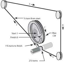
The advantage is that all your quality and wear issues should be sorted by the manufacturer and would be easily replaced if it broke. You could make this with a string rather than a belt as used in old fashioned variable capacitor radio tuners.

enter image description here

Figure 1. Image source: EDN.

You might be able to simplify further by using a multi-turn pot - a 10-turn, for example. A direct winding on a 6 mm shaft will require 18.8 mm per turn so ten turns would give you a 180 mm slide which might be good enough.

\$\endgroup\$
1
  • \$\begingroup\$ thanks, I'm thinking of something similar but using a smaller wheel and using a hall sensor to count turns \$\endgroup\$
    – Mridul
    Commented Mar 17, 2021 at 20:15
2
\$\begingroup\$

12 bit or 1/4k linearity is impossible to get even in commercial pots let alone DIY pots.

Get a rotary encoder or use a stepper with 200 steps per rev and use gear belts and pulleys to achieve the speed resolution tradeoff you need.

With my servo I had 8mm D pulleys with full steps up to 1m/s speed and 125 um resolution over 1.1m square area or in other words 13 bit resolution and accuracy. Using fraction steps could achieve more but wasn’t necessary.

Using 4:1 pulley reduction you can achieve the same over 25 cm span.

FWIW I used an UNO with CNC code , a CNC shield 12V and Gcode Panel S/W on a laptop set to 2A for 2X + 1Y motors. Awesome open source s/w. $250 for entire system :before mods. Sold to U of T for $4k after 2mos R&D searching for a solution.

\$\endgroup\$
2
  • \$\begingroup\$ What is the realistic resolution I can expect? I guess linearity can be calibrated in the code? \$\endgroup\$
    – Mridul
    Commented Mar 17, 2021 at 16:48
  • 1
    \$\begingroup\$ With thermal expansion , thickness variation and aging of material 1% perhaps if you are good (after wear in ) don’t guess \$\endgroup\$
    – D.A.S.
    Commented Mar 17, 2021 at 16:51
2
\$\begingroup\$

One possible solution would be to DIY a digital caliper. The patent has lots of info. It's basically a Vernier capacitive sensor. Here's an article of an implementation with an untethered slider which is what you want.

To be realistic though, you don't need your 25cm long slider to have absolute 12-bit accuracy unless your fingers are also accurate to about 60µm. So I'd drop the accuracy requirement, along with some of the linearity of course. If it is a musical instrument, stuff like reaction time and "it just works" are a lot more important.

A mutual capacitance slider seems like a good fit.

enter image description here

I think the triangles should be filled, though.

Capacitive sensors work best when sensing through thin material. The worst case is a finger on the other side of a thick plastic front panel. But if the finger is replaced with a small conductive plate (on the back of the slider "button") that slides on a thin film of mylar just on top of the PCB electrodes, then you'll get very good coupling.

Unlike an encoder, this has the innate advantage of absolute positioning, ie when the device is powered, it knows where its knobs are.

If the front panel is conductive, the whole thing will be shielded, so it should be robust.

For more accuracy, you can use more electrodes, or a Vernier arrangement.

\$\endgroup\$
2
  • \$\begingroup\$ Thanks! It appears a bit challenging to manufacture but would be a solid fit in my project \$\endgroup\$
    – Mridul
    Commented Mar 17, 2021 at 20:21
  • \$\begingroup\$ @Mridul It would be pretty straightforward to make on a PCB or flat-flex. Might be expensive given the length though. \$\endgroup\$
    – Hearth
    Commented Mar 20, 2021 at 15:01
1
\$\begingroup\$

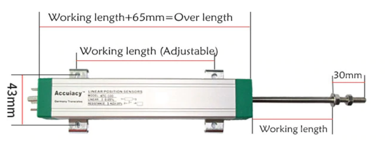
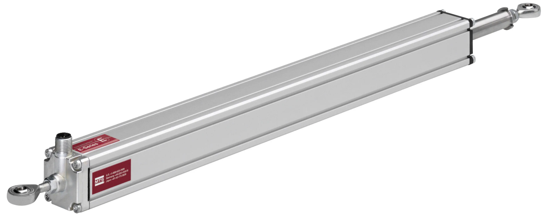
You can source resistive linear position sensors of the type used in plastic injection molding machines. 250, 275 or 300mm are standard lengths. Typical linearity spec is +/-0.1% or +/-0.05% (photos from Aliexpress and directindustry) when used as a voltage divider. Resolution is better than 12 bit. They're usually 5K\$\Omega\$ with a loose tolerance on the element resistance.

enter image description here

enter image description here

They're used to sense the position of the injection unit, mold and reciprocating screw in machines that operate industrially 24/7 with cycle times measured in seconds, so life is quite good.

\$\endgroup\$
0
\$\begingroup\$

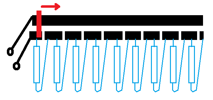
Use few (say 10 or 20) 1k normal resistors soldered in a line to make your line pot. Slider in red.enter image description here

\$\endgroup\$
5
  • \$\begingroup\$ Please provide a link or citation for the source of the images you copied into your answer. See electronics.stackexchange.com/help/referencing for more guidance. \$\endgroup\$ Commented Mar 20, 2021 at 12:30
  • \$\begingroup\$ I did not copy. Diy means do it yourself. This is my idea. He has asked proporse some idea. Already he has made a line with ressistive material. I did drow it. I have made this pot. It works well. \$\endgroup\$
    – upali
    Commented Mar 21, 2021 at 5:29
  • 1
    \$\begingroup\$ OP said, "I want to get 12 bits of resolution from the pot." You'll need 4095 resistors and 4096 contacts. And they have to fit in a 25 cm slider so the contacts need to be 0.06 mm from centre to centre. \$\endgroup\$
    – Transistor
    Commented Mar 21, 2021 at 9:42
  • \$\begingroup\$ Then it is impossible, isn't it? \$\endgroup\$
    – upali
    Commented Mar 21, 2021 at 11:46
  • \$\begingroup\$ OK, if the figure is your own drawing then that is fine. In this case the "DIY" refers to the potentiometer...it doesn't mean that every image here is created by the poster. \$\endgroup\$ Commented Mar 21, 2021 at 12:54

Your Answer

By clicking “Post Your Answer”, you agree to our terms of service and acknowledge you have read our privacy policy.

Not the answer you're looking for? Browse other questions tagged or ask your own question.