0
\$\begingroup\$

I'm looking to track the position of a pin on a shape display. I wanted to see if it's possible to make a PCB trace that could be put on the side of the pin and act as a potentiometer to gauge it's movement. Is this feasible, is there any way to strengthen the traces if i use a brush to make contact?

Here's an example of the sort of shape display/pin display that i'm thinking of. An accuracy of ±2 mm is all that's needed.

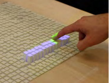
a shape display with each square being approximately 1x1 cm with a maximum vertical height of 10 cm

\$\endgroup\$
6
  • \$\begingroup\$ Anything simple you try will be terribly intermittent and oxide readily. SHow the photo of pin and accuracy needed with any constraints \$\endgroup\$
    – D.A.S.
    Commented Jul 12, 2020 at 17:20
  • \$\begingroup\$ Try looking for capacitive touch slider. Your laptop touchpad uses 2-D capacitive touch slider and is pretty accurate and long lasting. See if that works for you. \$\endgroup\$ Commented Jul 12, 2020 at 18:06
  • \$\begingroup\$ I can't see a pin in your photo. What is a "shape display"? Is it like a Braile display and is each display element a pin? Did you figure out what realistic resistance values you could make with a PCB trace of the length you are thinking of? \$\endgroup\$
    – Transistor
    Commented Jul 12, 2020 at 18:20
  • \$\begingroup\$ 'pin' is just used to describe the blocks that move up and down(because some displays have very small blocks, effectively pins). I'm more concerned with the robustness of a trace atm, i'm not sure if really thin traces would survive a brush constantly being in contact with them so was looking for ideas. \$\endgroup\$
    – aheigins
    Commented Jul 12, 2020 at 19:52
  • 2
    \$\begingroup\$ @Transistor 'at the moment' is a very common abbreviation in informal typed conversation \$\endgroup\$ Commented Jul 12, 2020 at 23:20

3 Answers 3

3
\$\begingroup\$

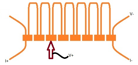
How much room do you have on the PCB? You could make a meander out of thin (1/4oz?) narrow copper traces, and have heavy pads for the slider/brush to contact. The narrow lines are covered in soldermask to protect them (not shown).

resistive meander in PCB copper

Then you do a 4-wire measurement of the resistance of the meander. You drive current through the meander at the "I+", "I-" lines, and the brush taps off the V+ (using V- as reference). You need a lot of current, and a sensitive milliVoltmeter.

\$\endgroup\$
1
  • 1
    \$\begingroup\$ Assuming the stated accuracy also implies a 2mm resolution, you can replace each meander with a surface mount resistor. \$\endgroup\$ Commented Jul 12, 2020 at 23:23
2
\$\begingroup\$

The simple answer is "no".

The problem is that copper has a very low resistance (which is why it's used in wires, right?). This means that for any reasonable current through it the voltage developed will be very small.

In your case, where you apparently want to indicate which discrete location (with a fairly small number of possibilities), it seems entirely possible, as long as you don't expect to use a pcb trace. Instead, you would use a resistor string to act as a discrete-level voltage divider, and make contact with the connection points. It would look something like Martin Stiko's answer, but with resistors instead of meanders.

\$\endgroup\$
1
\$\begingroup\$

Might I suggest investigating a solution based on capacitance instead of resistance? Most uCs support capacitive touch interfaces that can be setup for position/proximity detection without much fuss. You can even use it to detect water level. Seems like it migyt be a good fit. Just a suggestion.

\$\endgroup\$

Your Answer

By clicking “Post Your Answer”, you agree to our terms of service and acknowledge you have read our privacy policy.

Not the answer you're looking for? Browse other questions tagged or ask your own question.