0
\$\begingroup\$

I have a constant current LED driver which keeps the LEDs at about 5% glow when the AC side when the driver has its phase terminal connected to live power and its neutral terminal not connected to anything.

Detailed configuration under regular working wiring:
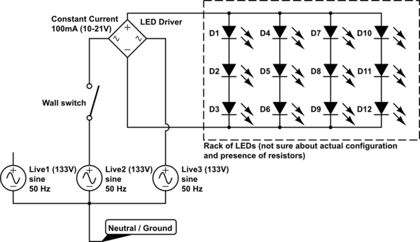
schematic

simulate this circuit – Schematic created using CircuitLab

Whilst trying to figure out a way to absorb the leaking energy so that the LEDs do get to 0% instead of 5%, I noticed some weird behaviours on the DC side of the driver:

  • Under the context described above (only one wire, live, on the AC terminals,) disconnecting one of the terminals on the DC side results in the LEDs still glowing, at about 0.5%; this is very very weak, but still there.
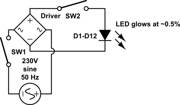
schematic

simulate this circuit

  • Then, keeping one of the DC terminals disconnected, but going back to connecting the AC terminals under a regular phase + neutral scenario, the LEDs are back glowing at 5%.
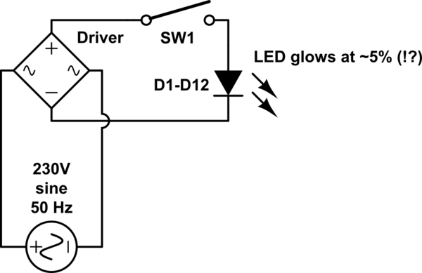
schematic

simulate this circuit

To sum up, after disconnecting one of the AC and one of the DC terminals of the driver, the LEDs are still getting some power in, even if very little. When I measured the voltage, it was around 3 volts, but I suspect this measurement was altered by the multimeter.

In my humble opinion, LEDs lighting up when one end of the circuit is disconnected from the source of power cannot be explained if we consider DC power.

Since the driver is a constant current supplier, I suppose the following is happening when a DC terminal is disconnected: "Infinite" resistance, which means the voltage gets very high, and might be sufficient for some current to travel through the diodes of the bridge rectifier, at counter current.

Is it possible that when this DC cable is disconnected, the voltage on the DC side of the bridge rectifier is so high that the diodes of this bridge cannot block the reverse voltage, and the DC terminals become AC terminals hence, propagating the capacitance effect from the AC side?

\$\endgroup\$
6
  • \$\begingroup\$ What is the grounding system in your area? Does the mains power in your building wiring include a grounding wire? If you have a volt-meter, what is the voltage between the neutral wire and the ground wire? \$\endgroup\$ Commented Jun 14, 2021 at 17:11
  • \$\begingroup\$ What LED trace width and path length? The current is free space capacitive leakage from an unbalanced high Vcm wire pair at high impedance with low currents on open V- and open N \$\endgroup\$
    – D.A.S.
    Commented Jun 14, 2021 at 18:07
  • \$\begingroup\$ @MathKeepsMeBusy I actually have no Neutral + Live, but a pair of 2 half Lives at 130V each (against Ground), combination of which gives 230V (see my second link in the question). There are many parameters in my case so I tried to keep things simple and this is why I mentioned the live terminal of the AC side of the driver was always connected. \$\endgroup\$
    – Ama
    Commented Jun 15, 2021 at 8:57
  • \$\begingroup\$ @TonyStewartEE75 I do not understand your question. \$\endgroup\$
    – Ama
    Commented Jun 15, 2021 at 8:58
  • \$\begingroup\$ Stripleds are like an antenna with stray coupling. What are the conductor dimensions ! \$\endgroup\$
    – D.A.S.
    Commented Jun 15, 2021 at 15:32

1 Answer 1

1
\$\begingroup\$

Have you checked how long the effect lasts for?

It's hard to say anything without a schematic and layout, but you may be inducing enough power on the other side of the open circuit to run the LED. LEDs can emit visible light with remarkably small currents, partially because our perception of light intensity is mostly logarithmic. I ask the above question because I've seen power bricks which continue to glow for several minutes after being unplugged, as they contain large amounts of capacitance.

If one of these mechanisms is what you're seeing, you may be able to fix it easily by placing a 1K-10K load resistor across the DC inputs to the current regulator. Again, a schematic would help us to be more specific and accurate.

\$\endgroup\$
3
  • \$\begingroup\$ Thanks! I will send some schematics later this week. I did try the 1K load resistor and it does not work. LEDs stay "on" for an unlimited time (well, at least 8 hours until sundown). \$\endgroup\$
    – Ama
    Commented Jun 15, 2021 at 8:58
  • \$\begingroup\$ I'm not seeing any filtering or constant current circuitry, or even limiting resistors, in your schematic above. However, it seems unlikely that inductive coupling to an open loop could power a 1K load for 8 hours. I suspect a connection not represented in the above schematics. \$\endgroup\$ Commented Jun 15, 2021 at 13:53
  • \$\begingroup\$ I have no idea what's inside the LED driver or the LED rack, I just represented the elements I am sure off. There are no additional cables at play, I disconnected the DC cable from the LED driver terminal, and there is now only one cable making any physical contact between the power of my house and this rack of LEDs. The physical contact goes AC cable x1 - LED Driver - DC cable x1 \$\endgroup\$
    – Ama
    Commented Jun 16, 2021 at 16:33

Your Answer

By clicking “Post Your Answer”, you agree to our terms of service and acknowledge you have read our privacy policy.

Not the answer you're looking for? Browse other questions tagged or ask your own question.