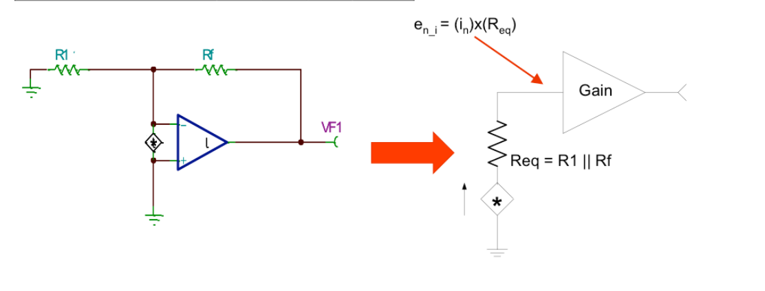
I am following this reference for noise calculations of a non-inverting op-amp.
I am not able to understand why the equivalent resistor is the parallel combination of R1 and RF as shown below:
I couldn't find any explanation for this anywhere. All application notes just state consider the parallel combination without any explanation.
Maybe I am missing something obvious here but while trying to analyse the circuit the current source is throwing me off.
Will virtual ground still be valid here now that a current source is present between the terminals?
If not, how do we go about this then? If yes, the inverting node becomes 0V, in which case all current should have flown through R1 as it gets shorted. In neither of the cases, do we get parallel combination of R1 and Rf.

