1
\$\begingroup\$

I have looked at this article, but it does not answer my question.

My question is: how would you go about measuring and/or calculating mathematically the self-parasitic inductance of a capacitor if I were to create one myself at home?

The link above just says that to find out what self-inductance value a cap has is to look in the datasheet of the manufacturer, but I will be making one from scratch.


I have also found this research paper where it talks about exact equations for the inductance of rectangular conductors, which is what a parallel plate cap is composed of.

And I found this equation for a self-inducting plate:

$$L = \frac{0.002}{3a^{2}}\left [3a^{2}l ln\left ( \frac{l+(l^{2}+a^{2})^{1/2})}{a} \right )-(l^{2}+a^{2})^{3/2}+3l^{2}aln\left ( \frac{a+(a^{2}+l^{2})^{1/2})}{l} \right )+l^{3}+a^{3} \right ]$$

Where a is the width of the plate and l is its length. This equation is under the 3rd section called: Self-Inductance Calculations, eq 18.


Would this equation (and others in the paper) work to finding the parasitic inductance of a homemade cap?

Incidentally: Would the type of material used in between the plates have any effect on the inductance? Like water, air, etc.

\$\endgroup\$
5
  • 2
    \$\begingroup\$ There are many (many) variables. If you've already made one, then connect a resistor to it, along with a frequency generator and oscilloscope, and view the waveform amplitude over frequency. The point where the amplitude is lowest and begins to rise again, is due to the parasitic inductance. From that frequency, you can get a ballpark idea of the inductance value. \$\endgroup\$
    – rdtsc
    Commented Aug 23, 2021 at 22:09
  • \$\begingroup\$ You would use an impedance analyzer (example: HP4194A) or a network analyzer that has impedance measuring capability. Sweep over a large enough frequency range and some analyzers can give you an equivalent circuit which includes the parasitic components. \$\endgroup\$
    – qrk
    Commented Aug 23, 2021 at 22:23
  • \$\begingroup\$ @qrk Is there any way to do it in theory? I don't have a big budget for equipment. \$\endgroup\$
    – Shocked
    Commented Aug 23, 2021 at 23:37
  • \$\begingroup\$ Material could make a difference depending on the magnetic permeability \$\mu_r\$ but it's likely to be close to 1 \$\endgroup\$ Commented Aug 24, 2021 at 4:25
  • \$\begingroup\$ There are ways to run simulation such as using FastHenry2; can't say this is simple to use, but there are example files. \$\endgroup\$
    – Ernesto
    Commented Aug 24, 2021 at 5:26

2 Answers 2

1
\$\begingroup\$

The ESL of a cap does not depend on its dielectric but only its electrode arrangement.

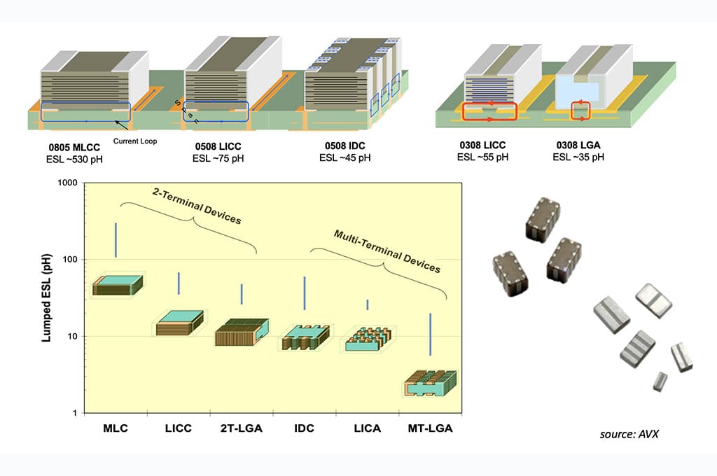
If you consider a standard two electrode capacitor, such as virtually all electrolytics and most ceramics, the ESL is given by the loop area that the current has to travel around when passing through the cap. The larger this loop, the larger inductance. The wider the electrode around loop, the lower inductance. Your equation seems to contain the relevant quantities.

The mounting style also matters a lot. THT parts have larger loops usually and thus higher inductance. Bring the terminals closely together and make the cap fit tightly over the PCB for minimum inductance. If you must use leads, then use a twisted pair for minimum loop area.

Here is a nice info graphic that qualitatively shows the impact of the current loop areas and electrode width (e.g. a wider cap with the same loop area will have a lower ESL):

enter image description here

\$\endgroup\$
6
  • \$\begingroup\$ What do you mean if the electrode is wider around the loop, then the inductance will be smaller? Is the loop a real physical thing in this case or something imaginary to help us with analysis? So the area of the electrode plate matters, the smaller, the smaller the inductance? \$\endgroup\$
    – Shocked
    Commented Aug 24, 2021 at 10:58
  • \$\begingroup\$ @Shocked The loop is a real thing: Current enters your cap through one lead, then goes through it along its internal electrodes and through the dielectric, and finally out the other lead (usually close by the first lead). So there is a loop area spanned by these "waypoints". The smaller this loop (the smaller the capacitor typically), the smaller the ESL. Even for the same loop area, one can bring down ESL however by using a wider electrode that leads around the loop. Large electrodes and small loop -> low ESL. \$\endgroup\$
    – tobalt
    Commented Aug 24, 2021 at 11:02
  • \$\begingroup\$ Could you find (if possible) a diagram of this happening, loop area, and its relationship with the area of the electrodes? I find it difficult to see what is going on here, especially the loop area for a cap because I see no loop in my mind. \$\endgroup\$
    – Shocked
    Commented Aug 24, 2021 at 11:08
  • \$\begingroup\$ I also have to say that current does not go through the cap, and if it does, then you do not have a good cap (it is broken). The whole idea is that current does not pass via the cap in the way you expect. The charges stay on either side of the cap (on the electrodes) but do not pass through the dielectric. \$\endgroup\$
    – Shocked
    Commented Aug 24, 2021 at 11:12
  • \$\begingroup\$ @Shocked we are talking ESL so this is obviously about AC current, which for all intents here does go through the cap, although - of course - no single charge carrier travels across any dielectric. I'll update my answer about the loop areas. \$\endgroup\$
    – tobalt
    Commented Aug 24, 2021 at 11:18
2
\$\begingroup\$

The easiest way to measure the self inductance of a capacitor is to use it to shunt a signal being supplied from some modest impedance signal generator (like 50 or 600 ohms, whatever test gear you have access to).

Vary the signal frequency, and measure the voltage across the capacitor.

  • At low frequency, the capacitive reactance is high, and the signal will be large.
  • At very high frequency, the capacitor will be very low impedance, and the reactance will be dominated by the parasitic inductance of the capacitor, the signal will again be large.
  • At the resonant frequency of the capacitance and the parasitic inductance, they will cancel each other out, and the capacitor will appear to be only its losses, which could be very low impedance, and the measured signal will be at a minimum.

Compute inductance from the resonant frequency and the known capacitance.

\$\endgroup\$
2
  • \$\begingroup\$ Is this method also safe for electrolytics due to the weak drive or must they be DC biased? \$\endgroup\$
    – tobalt
    Commented Aug 24, 2021 at 8:55
  • \$\begingroup\$ @tobalt I have done this with electrolytics, and I usually measure two identical ones, so that they can both be biassed properly. \$\endgroup\$
    – Neil_UK
    Commented Aug 24, 2021 at 9:29

Your Answer

By clicking “Post Your Answer”, you agree to our terms of service and acknowledge you have read our privacy policy.

Not the answer you're looking for? Browse other questions tagged or ask your own question.