0
\$\begingroup\$

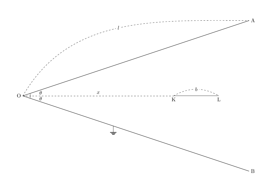
enter image description here

\$ \theta ~~\text{is assumed to be small} \$

The conductive rectangle exists which depth is \$a\$ and the length is \$2l\$ and it has been bent and grounded as the above diagram.

And the conductive rectangle KL exists which depth is \$a\$ and the length of it is \$b\$

The distance between the origin and the leftmost side of KL is \$x\$

We can assume that there is 2 capacitors are connected parallelly in the diagram.

\$ C=2 \int_{x }^{x+b } \frac{ \epsilon_{0} a }{ x \tan \left( \theta \right) } \,dx ~~ \leftarrow~~ \text{composed capacitance} \$

Currently I can't get the above equation.

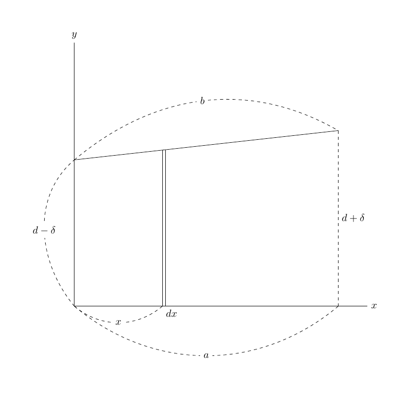
Firslty I introduce you the below formula which calculate the capacitance which each plate is not parallel(size and form is same) using infinitesimal capacitors.

This formula assuming that the plate is seperated by infinitesimal plates and the composed capacitance is calculated connecting the each infinitesimal capacitors parallely.

\$ C=\int_{0 }^{a } \frac{ \epsilon_{0} b }{ y(x) } \,dx \$

\$ a:= \text{width of the plate of capacitor} \$

\$ b:= \text{depth of the plate of capacitor} \$

\$ y(x):=\text{function which returns the distance between the plates as }x ~\text{proceeded from the leftmost side of the plate} \$ enter image description here \$ ~ \$
So bringing back

\$ C=2 \int_{x }^{x+b } \frac{ \epsilon_{0} a }{ x \tan \left( \theta \right) } \,dx \$

and think appyling the formula to it.

The current problem for me is that of the denominator \$x \tan \left( \theta \right) \$

Since the range of integration \$ \left[ x,x+b \right] \$,I guess that this integration only summing up the infinitesimal capacitors of range between the each edge of the capacitor KL

Is this integration really calculating the composed capacitance?

Why the integrations of left part( left from KL) and the right domain(right from KL)

are not done?

What I've been missing?

\$\endgroup\$
2
  • 1
    \$\begingroup\$ "This formula assuming that ... capacitors parallely.". 1 where did you find this formula? Please provide a link. 2 Is \$\theta\$ assumed to be small angle? 3 IMO, the integration from \$x \rightarrow x+b\$ is only correct under the assumption of parallel lines of electric field; which is a reasonable assumption when \$\theta\$ is small angle. \$\endgroup\$
    – AJN
    Commented May 28, 2021 at 11:51
  • \$\begingroup\$ Yes,\$\theta\$ is assumed to be small. \$\endgroup\$ Commented May 28, 2021 at 12:05

1 Answer 1

1
\$\begingroup\$

To find capacitance between two conductors from first principles, a test charge of Q is assumed to be moved from one body to the other. The energy spent in doing this per unit charge gives V. Q/C gives the capacitance.

For parallel plate capacitance, the electric field between the plates are assumed parallel. Most text books assume infinite plate dimensions for derivation so as to get a perfectly parallel electric field everywhere between plates. In practice, if the distance between the plates are much smaller than the dimensions of the plates, the parallel electric field assumption still hold good.

For your configuration, the electric field is not parallel due to the non parallel arrangement of the plates and difference in plate lengths. The figure drawn shows a very exaggerated non parallelism; I think. However, if the angle \$\theta\$ is small, the plates can be assumed mostly parallel and the electric field lines between the conductors can be assumed parallel without introducing much error in the result. for mostly parallel plates, the method of breaking it up into smaller capacitors is correct method.

Once the parallel plate condition is assumed, you need to integrate only the overlapping area of the plates; in this case the length of the smaller plate.

For large angles \$\theta\$, the result obtained this way will have significant error. For such cases you need to solve for the actual shape of the electric field and integrate appropriately.

\$\endgroup\$
1
  • \$\begingroup\$ So, needless to say that can we assume that the areas(left and right) of non-overlapping have very few electric lines of force which come out from the KL ? \$\endgroup\$ Commented May 28, 2021 at 12:17

Your Answer

By clicking “Post Your Answer”, you agree to our terms of service and acknowledge you have read our privacy policy.

Not the answer you're looking for? Browse other questions tagged or ask your own question.