1
\$\begingroup\$

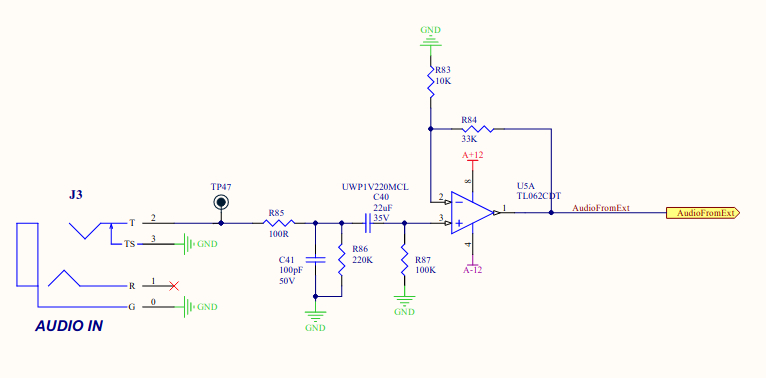
Filter schematic

This low-pass filter, taken from the Synthesizer Arturia Minibrute is rated at 15 MHz.

$$\frac{1}{2\pi RC} = \frac{1}{2\pi \times 100\Omega \times 100\text{ pF}} = 15,915,494.3092$$

Why would you aim so high?

Wouldn't a 68 nF do the job as well, or would it cost amplitude of a 10 V peak to peak signal?

$$\frac{1}{2\pi RC} = \frac{1}{2\pi \times 100\Omega \times 68\text{ nF}} = 23.4051386719\text{ kHz}$$

\$\endgroup\$
4
  • \$\begingroup\$ it's MHz not mhz. It's 15,915,494.3092 not 15.915.494,3092. The thoughts of the engineer are not recorded on the linked diagram (hence you are asking for an opinion) and, that linked diagram doesn't appear to relate to your circuit extract (hence my first reason to vote to close). \$\endgroup\$
    – Andy aka
    Commented Aug 31, 2021 at 9:54
  • \$\begingroup\$ @Andyaka, ya, it happens "sometimes" that if you copied a link, but you still have the previous on the clipboard, corrected. \$\endgroup\$ Commented Aug 31, 2021 at 9:57
  • \$\begingroup\$ @Andyaka 150915494,3092 is what the calculator returned, copied it from there and here we write: 15915494,3092, the decimals behind the comma. \$\endgroup\$ Commented Sep 1, 2021 at 4:33
  • \$\begingroup\$ It is not a bad idea to put a few 10's or 100's of pF on most inputs that can take it. This is for RF immunity. Especially in any circuit that has RF transmission capability (wifi, mobile phone, etc). Even digital inputs can benefit from small capacitors. \$\endgroup\$
    – user57037
    Commented Sep 1, 2021 at 16:14

2 Answers 2

2
\$\begingroup\$

There's one thing you missed out: The gain-bandwidth product of the operational amplifier.

Even if you are correct that the input filter has a cutoff frequency of 15.9 MHz in theory (neglecting the output impedance of the audio source), the actual cutoff is dominated by the operational amplifier because of the fact that the GBW of TL062 is 1 MHz.

enter image description here

So it's not possible that this amplifier has a cutoff frequency of higher than 1 MHz.

$$ \mathrm{ GBW = A_v \cdot BW \\ \Rightarrow 1\ 10^6 = (1+\frac{33k}{10k}) \cdot BW \\ \Rightarrow BW = 232.56\ kHz } $$

As you can see, the 100pF at the input filter does nothing for the audio input frequencies. So even if you remove that capacitor, the bandwidth will not change. However, there's a risk of radio frequencies being picked up if the input comes from a very long cable (thus the cable acts as an antenna). The input filter helps these frequencies to be chopped off for the sake of the amplifier's stable operation.

If you have a chance, I suggest you simulate the circuit.

PS: It's not uncommon for the audio equipment to have cutoff frequencies higher than audible frequencies (e.g. 150kHz).

\$\endgroup\$
6
  • \$\begingroup\$ Thank you very much for the info, I'm trying to build a Long tail transistor VCA for my modular synthesizer, you can spot it on my profile, i wanna do the best possible job while designing the PCB. i can try at multisim.com at most, which is where i simulated the workings of my VCA design. your information was very good. so you suggest to keep the 100pF capacitor? \$\endgroup\$ Commented Aug 31, 2021 at 10:30
  • 1
    \$\begingroup\$ @NaturalDemon so you suggest to keep the 100pF capacitor? you can keep it. It has nothing on audible frequencies. But, as I stated in my answer, it helps the radio frequencies to be chopped off for the sake of the amplifier's stable operation. \$\endgroup\$ Commented Aug 31, 2021 at 10:36
  • \$\begingroup\$ ok, thank you for your advice and your time. \$\endgroup\$ Commented Aug 31, 2021 at 10:39
  • \$\begingroup\$ i have 2 audio inputs on a 100K summing bus, can i place the 100R and 100pF in front of those 100K resistors? the 100K is standard for modular synthesizers. \$\endgroup\$ Commented Aug 31, 2021 at 10:53
  • 1
    \$\begingroup\$ @NaturalDemon can i place the 100R and 100pF in front of those 100K resistors? Normally that's what you should do. Because, if you place the 100p after summing, the 100p capacitor will interact with those 100k resistors and make the cutoff frequency way lower. PS: The comments section under an answer is not a suitable place for asking related questions. You should have posted a new question and indicate this current question as "related". Anyway, do this way next time. \$\endgroup\$ Commented Aug 31, 2021 at 11:58
2
\$\begingroup\$

The impedance of an audio source would not be 0 ohms so the filter frequency would not be 16 MHz.

That's why also 68nF you suggest is a bad idea, if source impedance is 1 kohm, the cutoff frequency would be 2 kHz.

Typically audio inputs of professional devices have an RF blocking capacitor to filter out high frequency signals from getting to the amplifier input and cause problems in the amplifier which can't handle them, or to prevent high frequency signals from leaking out from the device.

\$\endgroup\$
0

Your Answer

By clicking “Post Your Answer”, you agree to our terms of service and acknowledge you have read our privacy policy.

Not the answer you're looking for? Browse other questions tagged or ask your own question.