2
\$\begingroup\$

I'm designing a PCB that uses a ESP32-D0WD-V3 QFN 5x5 and I want to have a uFL port for 2.4Ghz Wifi/BLE. Directly from the datasheet, I get the following note:

The output impedance of the RF pins of ESP32 (QFN 6x6) and ESP32 (QFN 5x5) are (30+j10) Ω and (35+j10) Ω, respectively. A π-type matching network is essential for antenna matching in the circuit design. CLC structure is recommended for the matching network.

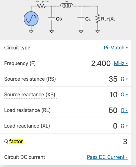
Following the datasheet, I went into https://www.omnicalculator.com/other/impedance-matching and filled the blanks like so:

RF matching calculator

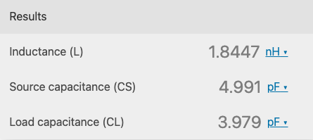
Results of the calculator

The results of the calculator

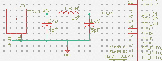
Resulting schematic

enter image description here

I have no experience with RF design or impedance matching. Can someone advise if my steps are correct and give some pointers into what can I improve?

\$\endgroup\$
3
  • \$\begingroup\$ I get the same sort of capacitor and inductor values for the pi network using my calculations. This assumes that the antenna is of course 50 ohm and not more complex. \$\endgroup\$
    – Andy aka
    Commented Dec 10, 2021 at 19:01
  • \$\begingroup\$ @Andyaka Thank you. Yes, I'm planning to run 50-ohm antennas. \$\endgroup\$
    – Kamil
    Commented Dec 10, 2021 at 19:37
  • 1
    \$\begingroup\$ Add a 47pF DC blocking capacitor, most antennas at this band are short at DC. \$\endgroup\$
    – Lior Bilia
    Commented May 14, 2023 at 10:45

1 Answer 1

1
\$\begingroup\$

In addition, I would also place the pi-network as close as possible to the RF output pin since it is at this node where the impedance isn't 50 Ohm and you want the output to look 50 Ohms when a received signal travels from the antenna to the RF pin.

Assuming the antenna is already 50 Ohms, a transmit signal should no have no issues as it travels from the RF pin to the antenna, provided that the line impedance is also 50 Ohms.

Of course if all the relevant components are really "close" together (approximately \$ \leq0.1\lambda\$), this becomes less of an issue.

\$\endgroup\$
1
  • \$\begingroup\$ Thank you for your feedback. Yes, I plan to place that pi network very close to LNA_IN pin, and then make sure the trace impedance is 50ohm all the way into the uFL connector. As for the antenna, I will be getting only 50ohm antennas. \$\endgroup\$
    – Kamil
    Commented Dec 10, 2021 at 21:40

Your Answer

By clicking “Post Your Answer”, you agree to our terms of service and acknowledge you have read our privacy policy.

Not the answer you're looking for? Browse other questions tagged or ask your own question.