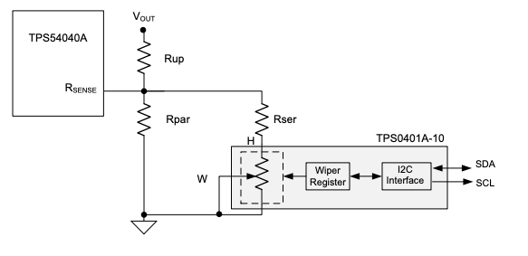
I'm currently work through an application note from Texas Instruments about building a programmable power supply. The base concept is fine and I understand it, now I'm trying to go through the calculations and I really got stuck as all values I'm calculating are not matching towards the results in the example. I need help and someone who can guide me through the calculations in the hope I learn enough to not get stuck on this in the future.
Application Note: https://www.ti.com/lit/ug/tidu533/tidu533.pdf
I'm currently get stuck at 4.2.2 where the resistors of the resistor network get calculated to implement the digital potentiometer.
So from my understanding you first need to calculate the "low" part and then use the overall value of it to calculate the "up" part by the formular found at the beginning of the section.
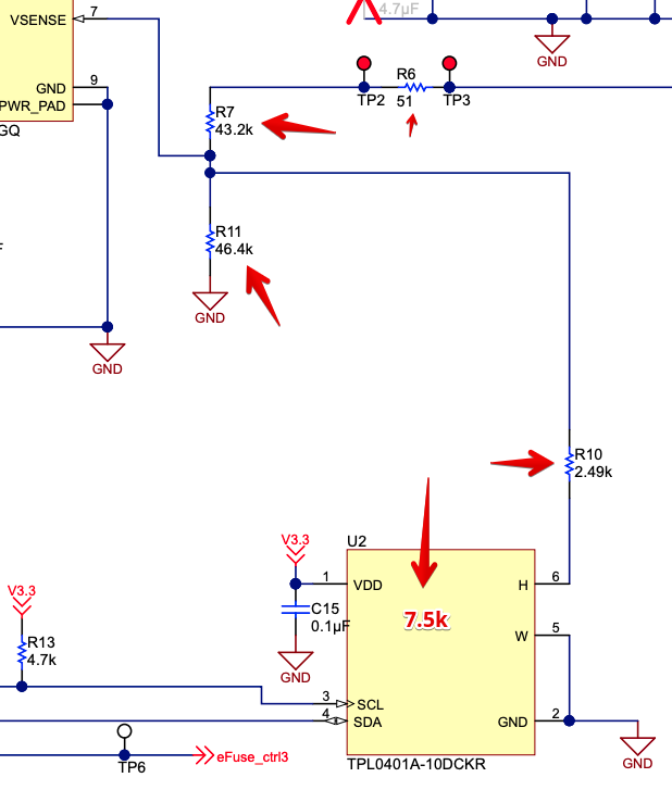
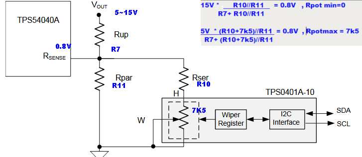
In the "low" section (connected to ground) the resistors Rpar and Rser are both already taking care that the voltage will not exceed 15V no matter if the digital potentiometer is already initialized (set to the right value I mean) or not. However, the combination of Rpar, Rser and the potentiometer and it's calculation is to hard for me at the moment. There are the needed formulas in the doc at page 13, but no matter what I calculate, they will never match the final results from the schematics.
Values used in the example of the application note:
| Name | Value |
|---|---|
| Vmax | 15V |
| Vmin | 5V |
| R10 | 2.49k |
| Rpotmin | 0k |
| Rpotmax | 7,5k |
| Vref | 0,8V |
Final values in the Schematics of the application note:
Anyone has an idea how I can best move on with this one? Maybe someone can guide me through the calculations and then I can make an example with my own values and someone can approve them?
Thanks a lot in advance,
Ben


