0
\$\begingroup\$

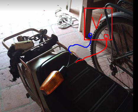
I own a motorbike that runs with a 6V (yes, 6V) electric system and I'm designing some LED lamps for it. My current design is dead simple, here is a falstad simulation, it's just two 1W 2.5V drop LEDs in series with a current limiting resistor.

The bike's electric system consists of an alternator outputting presumably some ACish waveform that gets somewhat rectified and "regulated" to never exceed 6V but is not smoothed with capacitors at any point.

These lamps are for turn signals. The circuit that controls the intermitent blinking of the lights is an ancient thermal relay in series with the lamps that probably has some unknown voltage drop.

The thing is, when you accelerate the voltage in the system increases and when the bike is at idle, the voltage drops, this is obvious because you can see the lamps visibly get brighter, here is a short video I shot.

Now this is what I can't figure out. While measuring the voltage drop on the lamp, I'm just measuring around 1.6V, I'm doing this measurement with a TRUE RMS AC good quality multimeter (UNI-T UT 61E). Such a measurement should be impossible, since the LEDs have a voltage drop of 2.5V each (I measured both of them) and they are in series and they DO light up. While measuring in DC I get constantly changing voltages (expected.)

enter image description here

If I measure AC current with the true RMS multimeter the result is even more jarring. I get around 0.7A to 1.1 A depending on how much I turn the accelerator (yes I connected the multimeter in series with the LEDs.)

This is weird since the maximum current of those LEDs is around 300mA (1Watt rating with a voltage drop of 2.5V, and they are in series), meaning that if 1A were to circulate through them they should be terribly bright and hot to the touch, However they are cool to the touch and not that bright. Also the current-limiting resistor would never allow 0.7 amperes unless the voltage was much greater.

I'm confused, the multimeter is almost new and I have measured DC before with great results. Can anyone speculate what is going on?

I have no osciloscope to do any signal analysis.

\$\endgroup\$
11
  • 1
    \$\begingroup\$ "While measuring in DC..."- So you were measuring the lamp voltage on a DC voltage range when running the engine? What voltage did you read on the battery while doing this? What model is your motorbike? Can supply the circuit diagram of the bike? \$\endgroup\$ Commented Feb 12, 2022 at 21:10
  • \$\begingroup\$ Yes, but i I just measured in DC just out of confusion, I expected to measure in True RMS AC as my actual intended measurement. The voltage of the battery is 6.4V the motourbike is a suzuki AX 100 and here is the diagram, however the original one is unregulated and uses a resistor and a diode, I removed those and added a 6V regulator that is specifically designed to replace those for this bike. 3.bp.blogspot.com/-QWBZbCpJ7mc/T2h_okxKZhI/AAAAAAAAAkM/… \$\endgroup\$ Commented Feb 12, 2022 at 21:14
  • \$\begingroup\$ just to clarify I expect my waveforms to be a half rectified AC waveform with a peak of 6V and a minimum value of 0V \$\endgroup\$ Commented Feb 12, 2022 at 21:20
  • 2
    \$\begingroup\$ "the original one is unregulated and uses a resistor and a diode, I removed those and added a 6V regulator" - can you show us the circuit of this mod? \$\endgroup\$ Commented Feb 12, 2022 at 21:46
  • 1
    \$\begingroup\$ I should have watched the video earlier. Turn indicator is flashing too rapidly for the meter to measure accurately. You should use an electronic flasher unit to get the correct flash rate. Why do you expect your waveforms to be 'half rectified AC'? \$\endgroup\$ Commented Feb 12, 2022 at 21:52

1 Answer 1

1
\$\begingroup\$

The RMS is presumably low because the meter is measuring AC and may be discarding the DC component - some meters have an explicit AC+DC setting. The meter is doing its best to make sense if a waveform that’s 6V some of the time and zero at other times. The current reading is more of a mystery but I’d speculate that again it’s to do with the current not being AC - it’s not DC but certainly shouldn’t be alternating.

\$\endgroup\$
3
  • \$\begingroup\$ yeah both voltage and current are most likely half rectified waveforms \$\endgroup\$ Commented Feb 12, 2022 at 21:16
  • \$\begingroup\$ As said in the other comments, It's also posible that the flashing rate is too fast for the meter to get an accurate RMS reading. \$\endgroup\$ Commented Feb 12, 2022 at 22:35
  • \$\begingroup\$ True - typically meters are designed for 50-60Hz, I think my Fluke 87 is rated to 1kHz or so. 3 phases at 9000rpm would fluctuate at 450/sec so quite possibly that’s an issue \$\endgroup\$
    – Frog
    Commented Feb 12, 2022 at 23:13

Your Answer

By clicking “Post Your Answer”, you agree to our terms of service and acknowledge you have read our privacy policy.

Not the answer you're looking for? Browse other questions tagged or ask your own question.