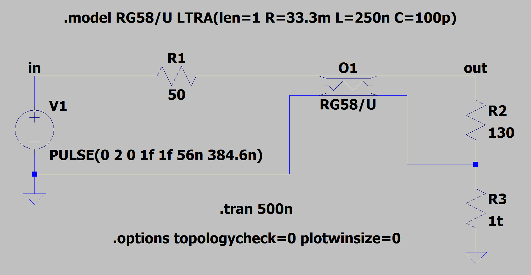
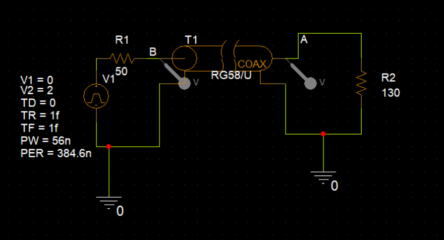
I'm not a PSpice user, but I believe I correctly duplicated your circuit in LTspice. The fact that you required the len parameter specified tells me that the RG58/U coax symbol you're using infers a lossy transmission line model (i.e. the LTRA model). I plugged in some per-unit RLC values for 20AWG RG58/U coax I found on the web and came up with what's below for a 1 meter length of it. I disabled LTspice's topology checker via the .options statement since it tries to "fix" certain problems on its own and I want it to behave more like PSpice right now. It of course gives me an error because of this.
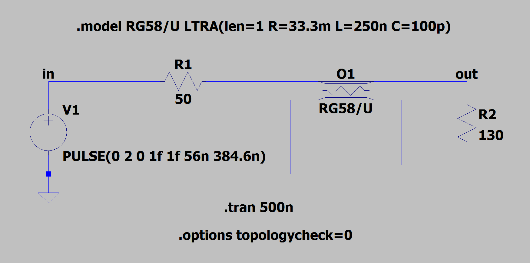
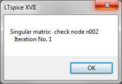
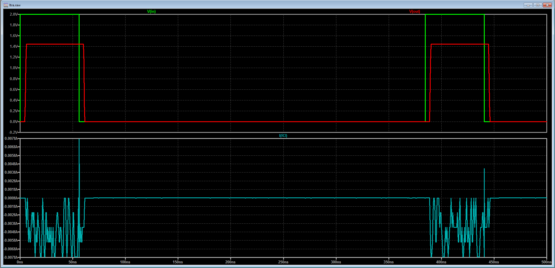
Node N002 is the node at the bottom of R2 and is considered "floating" to the underlying SPICE engine. Knowing roughly how the SPICE engine calculates things, every node needs a DC path to ground (i.e. the "zero" node) to be able to formulate and solve the circuit matrix. This far side of the transmission line needs a DC reference in order for the matrix math to work. Like you mentioned in the question, you can put a ground directly at this node to solve the problem. However, if that bothers you then you can also opt to connect it to ground via a very low conductance (high resistance) such as 1t or 1g. This still satisfies the requirement of the SPICE engine, and will allow the simulation to execute properly. No current ends up flowing through this resistor, except maybe some noise due to numerical artifacts of the calculations (as shown below in the sub-femtoamp range).
NOTE: A similar scheme is also required for isolated transformer simulations, for the same reason.
