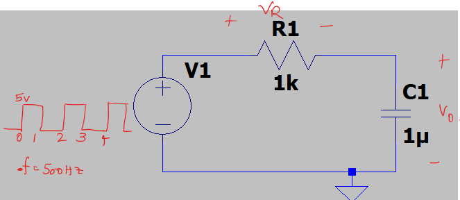
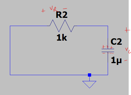
Were you to solve the differential equations for this circuit, you would find that the voltage across the capacitor always is predicted by this equation:
\begin{align}
V_C(t) &= V_\mathrm{f} + \left( V_\mathrm{i} - V_\mathrm{f} \right) e^{-t/\tau},
\end{align}
where the time is measured from some initial point—the start of each half cycle here—when its voltage is \$V_\mathrm{i}\$ and would end it at \$V_\mathrm{f}\$ if it were allowed to change smoothly through infinite time. The constant \$\tau\$ is the time constant: \$\tau=RC\$.
You can easily see that at time \$t=0\$ this equation does indeed predict \$V_C = V_\mathrm{i}\$ and at time \$t=\infty\$, \$V_C = V_\mathrm{f}\$. The voltage across the capacitor always moves toward the value of \$V_1\$, so that's the appropriate value for \$V_\mathrm{f}\$ for any interval under consideration. Of course, \$V_1\$ changes at the beginning of every half cycle. Given \$V_1\$ and \$V_C(t)\$, Kircholff's voltage law let's you compute \$V_R(t)\$:
\begin{align}
V_R(t) &= V_1 - V_C(t).
\end{align}
Assuming that the initial voltage across the capacitor at time \$t=0\$ is 0 V, then for the half cycle when \$V_1\$ goes high,
\begin{align}
V_C &= V_1\left( 1 - e^{-t/(RC)} \right) \\
V_R &= V_1 e^{-t/(RC)} .
\end{align}
Since the time constant \$ \tau = RC = 1 \mathrm{~ms} \$, after this time we have
\begin{align}
\Bigl. V_C(t) \Bigr|_{t=1\mathrm{~ms}} &= (5\mathrm{~V}) \left( 1 - e^{-1} \right) \\
&= 3.16\mathrm{~V} \\
\Bigl. V_R(t) \Bigr|_{t=1\mathrm{~ms}} &= (5\mathrm{~V}) e^{-1} \\
&=1.84\mathrm{~V}.
\end{align}
These constitute the initial conditions for the next half cycle, but now \$V_1=0\$, so
\begin{align}
V_C(t) &= (3.16\mathrm{~V}) e^{-(t-1\mathrm{~ms})/(RC)} \\
V_R(t) &= -V_C(t).
\end{align}
At time \$t=2\mathrm{~ms}\$ we have
\begin{align}
V_C &= (3.16\mathrm{~V}) e^{-1} \\
&= 1.16\mathrm{~V}\\
V_R &= -1.16\mathrm{~V}.
\end{align}
For the third half cycle, unlike the first one, the capacitor starts with a non-zero voltage across it, namely, \$1.16\mathrm{~V}\$. This means the initial voltage across the resistor becomes
\begin{equation}
\Bigl. V_R(t) \Bigr|_{t=2\mathrm{~ms}} = 5\mathrm{~V} - 1.16\mathrm{~V} = 3.84\mathrm{~V}.
\end{equation}
The voltage across the capacitor during this half cycle is
\begin{align}
V_C(t) &= 5\mathrm{~V} + (1.16\mathrm{~V} - 5\mathrm{~V}) e^{-(t - 2\mathrm{~ms})/(RC)}\\
V_R(t) &= 5\mathrm{~V} - V_C(t) \\
&= (5\mathrm{~V} - 1.16\mathrm{~V}) e^{-(t - 2\mathrm{~ms})/(RC)}.
\end{align}
For \$t=3\mathrm{~ms}\$, this is
\begin{align}
\Bigl. V_C(t) \Bigr|_{t=3\mathrm{~ms}} &= 5\mathrm{~V} + (1.16\mathrm{~V} - 5\mathrm{~V}) e^{-1} \\
&= 3.59\mathrm{~V} \\
\Bigl. V_R(t) \Bigr|_{t=3\mathrm{~ms}} &= 5\mathrm{~V} - 3.59\mathrm{~V} \\
&= 1.41\mathrm{~V}.
\end{align}
The process continues until a steady state is reached. Here the term ``steady state'' means that the voltages across the capacitor at the start of each cycle have the same absolute value, and similarly for the resistor.
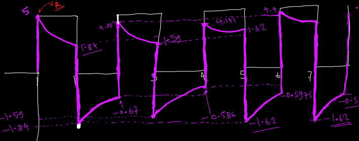
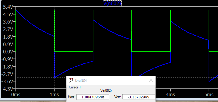
The voltages across the resistor at the beginning and end of the three half cycles analyzed in detail here match those shown in the output of your LTspice simulation:
\begin{align}
5\mathrm{~V} &\to 1.84\mathrm{~V} \\
-3.16\mathrm{~V} & \to -1.16\mathrm{~V} \\
3.84\mathrm{~V} &\to 1.41\mathrm{~V}.
\end{align}
Steady State Solution
When the system reaches a steady state, what are the maximum and minimum capacitor voltages?
Here, again, is the general solution given above to the differential equations describing this system:
\begin{align*}
v(t) &= V_f + (V_i - V_f) e^{-t/\tau}
\end{align*}
When the voltage supply's output is high, and if it nevery changed, the capacitor's voltage eventually would settle at \$V_f = V_\text{s}\$.
When it is low (zero), it would settle at \$V_f = 0\mathrm{~V}\$.
Assume initially that the power supply outputs a zero voltage. Then
\begin{align*}
v(\tau) &= V_{f_1} + (V_{i_1} - V_{f_1}) e^{-1}\\
&= V_{i_1} e^{-1}
\end{align*}
where \$V_{f_1}\$ is the capacitor voltage as time goes to infinity and \$V_{i_1}\$ is the voltage at the beginning of the time interval.
This is the initial voltage for the second interval, so
\begin{align*}
v(\tau) &= V_{f_1} + (V_{i_1} - V_{f_1}) e^{-1}\\
&= V_{i_1} e^{-1}
\end{align*}
At this point the power supply switches to output voltage
\$V_\text{s}\$. If we let \$V_{f_2}\$ be the capacitor voltage that would arise in this interval if the voltage supply's output did not change and if time went to infinity, then \$V_{f_2} = V_\text{s}\$. Also let \$V_{i_2}\$ be the voltage at the beginning of the second interval. It is the same as the voltage \$V_{f_1}\$ at the end of the first interval. Then
\begin{align*}
v(2\tau) &= V_{f_2} + (V_{i_2} - V_{f_2}) e^{-1} \\
&= V_\text{s} + \left( V_{i_1}.e^{-1} - V_\text{s} \right) e^{-1},
\end{align*}
The exponential \$e^{-1}\$ because it is assumed that each phase of the waveform takes a single time constant \$\tau\$. (Since both parts of the full cycle take the same amount of time, the duty cycle \$\delta=50\%\$.)
At steady state we expect the capacitor voltage to have returned to its initial state, that is, \$v(2\tau) = V_{i_1}\$,
so
\begin{align*}
V_{i_1} &= V_\text{s} + \left( V_{i_1} e^{-1} - V_\text{s} \right) e^{-1}
\end{align*}
Gathering like terms gives
\begin{align*}
V_{i_1} \left( 1 - e^{-2} \right) &= V_\text{s} \left( 1-e^{-1} \right).
\end{align*}
Solving for \$V_{i_1}\$ gives
\begin{align*}
V_{i_1} &= V_\text{s} \left( \frac{1-e^{-1}}{1 - e^{-2}} \right) \\
&= 0.731 V_\text{s}.
\end{align*}
If \$V_\text{s}=5\mathrm{~V}\$, then \$V_{i_1}=3.655\mathrm{~V}\$. We now can compute
\begin{align*}
V_{f_1} &= V_{i_1} e^{-1} \\
&= 1.345\mathrm{~V} \\
&= V_{i_2}.
\end{align*}
We can check that \$v(2\tau) = v(\tau)\$:
\begin{align*}
v(2\tau) &= V_\text{s} + \left( V_{i_2} - V_\text{s} \right) e^{-1} \\
&= V_\text{s} + \left( V_{f_1} -V_\text{s} \right)e^{-1} \\
&= 5\mathrm{~V} + \left( 1.345\mathrm{~V} - 5\mathrm{~V} \right) e^{-1} \\
&= 3.655\mathrm{~V}.
\end{align*}
This is the same as \$V_{i_1}\$, showing that the capacitor voltages do, indeed, oscillate between \$1.345\mathrm{~V}\$ and \$3.655\mathrm{~V}\$.


