OK, the datasheet is pretty explicit about what type of capacitor this is...

First, the replacement needs to fit on the board, so it needs the same pin spacing. It can be taller or wider, if there is space available. Picking a 105°C cap is always a good idea, motherboards tend to be pretty hot.
Voltage and capacity of the replacement cap should be the same or higher. While a higher voltage rating won't cause trouble, a higher capacitance can cause some problems like higher inrush current.
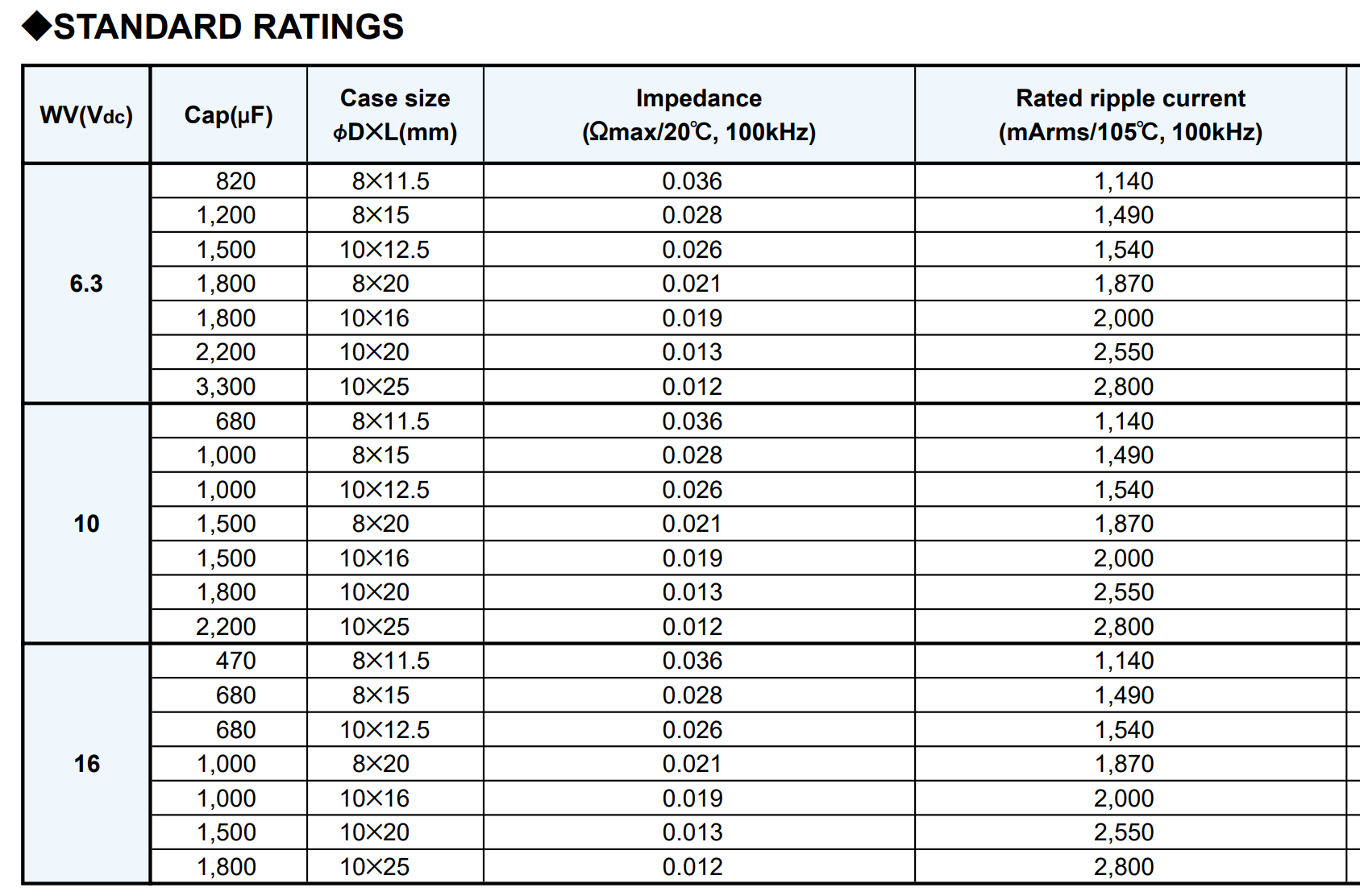
Then, you have to check the impedance (not the inductance):

Impedance and ripple current are measured at 100kHz, which is a de facto standard for low-ESR caps meant to be used in switching power supplies.
Impedance is the sum of the capacitor's capacitive impedance, its internal resistance (ESR) and its inductive impedance, which depends on its construction. Since the value of interest for filtering a switching regulator output is the impedance, the manufacturers just list that, for convenience.
As for ripple current, it should be the same or higher.
The ripple current limit is due to self-heating. AC current in the cap dissipates power in its internal resistance (ESR) which heats the cap from the inside. When the ripple current spec is exceeded on a capacitor, it overheats and its life is shortened, or if you exceed it by a lot, sometimes it just pops. So, the replacement cap having higher ripple current rating is not a problem. It'll just heat less and last longer.
You should pick a similar or lower impedance/ESR. It's generally not recommended to overdo it, for example if you replace a "low ESR" electrolytic with an ESR in the tens of milliohms with a polymer cap in the single digit milliohms, you would have to check if it is at the output of a regulator, and then check the datasheet of this regulator for what kind of ESR it requires for stability. So it's best to pick something similar.
You should also check other caps of the same series on the board. If the caps were faulty, maybe there are other dead ones.
To clear up the confusion about inductance: this one depends pretty much only on the area of the loop taken by the current inside the cap. So, capacitors with wider pin spacing have a higher loop area, therefore they have more inductance and poorer high frequency performance. That's why your CPU VRM has many small caps in parallel instead of just a large one: physically smaller caps have lower inductance, and on top of that, putting several in parallel further improves the total impedance.
This also means you should not leave extra lead length when soldering the capacitor. The bottom of the cap should touch the board, it should not stand on its legs.


