1
\$\begingroup\$

enter image description here

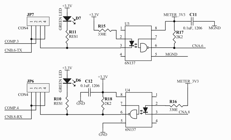
I have the following circuit for an isolated serial port. 6N137 is a high speed opto, so baud rate is not an issue.

The problem with this is that it works only 1 way i.e. CNB -> CNA transmission works ok however CNA->CNB TX does not work.

Swapping them around does not solve the issue. Transmission works only 1 way.

I have tested this on a breadboard at low baud rates (9600 baud). After eliminating some initial loose connections the problem still persists. I have individually tested and measured every component in this circuit and all of them are fine.

Any suggestions are appreciated on the following points:

  1. Is this circuit correct or does it need some additional pull-ups/pull-downs/caps?
  2. Are R15,R17, R16, R18 values correct or does it need tweaking around? Datasheet for 6N137 states that R17, R18 should range between 330-4k ohm. I have experimented around all values between that range with no luck.
  3. Suspecting damaged 6N137 I have tried with multiple other ICs with no luck. All ICs work fine when individually tested.
  4. I do not have access to a scope. Will probing with a scope help here?
\$\endgroup\$
9
  • 1
    \$\begingroup\$ Circuit seems fine. Show pics of layout? Have you confirmed that communication is functional without isolation? \$\endgroup\$ Commented Jul 17, 2022 at 10:01
  • \$\begingroup\$ Yes. Tested multiple times on multiple laptops, USB ports. Works perfectly fine without isolation. \$\endgroup\$
    – Satkarni
    Commented Jul 17, 2022 at 10:25
  • \$\begingroup\$ With isolation, also works perfectly fine one way for all baud rates (9600-115200). I am at a loss to get it to work both ways. I have tested this on a breadboard, so layout issue is not relevant. \$\endgroup\$
    – Satkarni
    Commented Jul 17, 2022 at 10:27
  • \$\begingroup\$ Are you possibly exceeding the max output drive current? \$\endgroup\$
    – Velvet
    Commented Jul 17, 2022 at 10:44
  • 3
    \$\begingroup\$ Probing with a scope is almost always useful when trying to troubleshoot a circuit. Even if a scope probe fails to reveal the source of a problem, it will almost always allow you to narrow the possibilities, and show you parts of a circuit that are working correctly. \$\endgroup\$ Commented Jul 17, 2022 at 17:59

2 Answers 2

2
\$\begingroup\$

Is this circuit correct or does it need some additional pull-ups/pull-downs/caps?

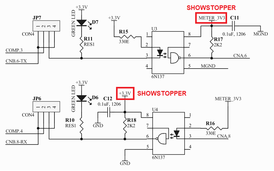
Vcc on the 6N137 (pin 8 with respect to pin 5) has to be at least 4.5 volts: -

enter image description here

You are running your Vcc supply at 3.3 volts and that is a showstopper: -

enter image description here

Data sheet image from here.

\$\endgroup\$
4
  • 1
    \$\begingroup\$ I am using 6N137-L (Liteon Optoelectronics) which works on 3.3V. \$\endgroup\$
    – Satkarni
    Commented Jul 17, 2022 at 10:24
  • 1
    \$\begingroup\$ Then you should add that information as an edit section at the bottom of your question and make it clear that this edited text was only provided by you after I gave my answer. \$\endgroup\$
    – Andy aka
    Commented Jul 17, 2022 at 10:36
  • 1
    \$\begingroup\$ You should also make sure that the ones you have purchased are not from an early batch of devices from Lite-on because early ones did not run below 4.5 volts. There are data sheets that demonstrate this such as here. \$\endgroup\$
    – Andy aka
    Commented Jul 17, 2022 at 10:49
  • 1
    \$\begingroup\$ @Andyaka Wow, why even bother adding the -L? And they ruined CMI, 1kV/µs at 20V, how useless; even though the headline still claims 15! The recent version looks good; but it's unclear how available it is, Digi-Key for example lists the non-L datasheet and version. Too much uncertainty -- I would not design-in this part. Good catch. \$\endgroup\$ Commented Jul 17, 2022 at 16:53
2
\$\begingroup\$

After further experimentation, the issue turned out to be a loose connection on a breadboard column. I had tried to change all components, wires, USB-serial adapters but the defective breadboard was common throughout all these experiments.

Due to the loose connection, the supply to one of the opto isolator was erratic, hence the circuit only worked 1 way.

\$\endgroup\$
2
  • 1
    \$\begingroup\$ You should edit the original question to avoid misunderstanding and comments that no longer apply. \$\endgroup\$
    – PStechPaul
    Commented Jul 24, 2022 at 5:29
  • \$\begingroup\$ I had already edited the original question. But my edit was rolled back by other users. I leave it to stack overflow ego maniacs to sort out the editing process themselves. \$\endgroup\$
    – Satkarni
    Commented Jul 24, 2022 at 6:30

Your Answer

By clicking “Post Your Answer”, you agree to our terms of service and acknowledge you have read our privacy policy.

Not the answer you're looking for? Browse other questions tagged or ask your own question.