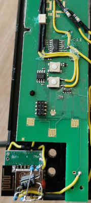
I am trying to switch a roller shutter belt winder (RADEMACHER RolloTron Basic 1100) with an AI-Thinker ESP8266 ESP-12E module. As software ESPhome is used.
Most of the time the ESP8266 loses its wifi connection on triggering the open or close function. Often it does only one action. Sometimes I can open or close 2 - 3 times before the wifi is gone.
I already tried a lot of things and now I am running out of ideas:
- Ok, probably a overload/interference on GPIO12 or 14 => Disconnected them and pressed the button on the unit instead - same problem
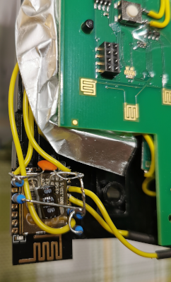
- Then it is a problem with the power supply => A D-Sun 3Ampere step down regulator should be enough. Just to be sure I also added a 33uF and a 10nF capacitor (the ones visible in the picture.) I even tried 470 uF across the terminals - no effect. Also I could not see any obvious peaks on the little DSO138 oscilloscope (I know, it's not the best for this job.)
- Sure it's not the power supply? Ok, power the ESP by battery - same effect
- Is the chip entirely down? - I programmed GPIO13 to also trigger the down button. If the wifi is lost the down button is correctly triggered on adding a pull up resistor to the GPIO13. So it is indeed only the wifi that's gone. Furthermore I added 10nF ceramic capacitors to CH_PD and RESET to ensure this pins are kept high, also without success.
- Its a bug in ESPHome? No: the same happens with Tasmota
- The signal is too bad. Moved directly in front of the router and also disabled non-standard temporary - same problem
- Played around with shielding (aluminum foil wrapped in tape) - did not help.
Update 1:
I did tests with another battery powered ESP-12E that has no connection to the shutter winder. The wifi issues are starting at distances around 5 cm (1.95 inches). 10 centimeters away the second esp is working just fine. Also i noticed resets around every 10th time a shutter button is pressed (the ESPs led was blinking once)
Furthermore i tested the other way round with the original setup: If the opto-isolator are disconnected and the wires are just connected to two leds there are no issues - even that close to the shutter winder. The leds can be switched over wifi without resets or wifi issues.
So it seems to have to do with interference (probably caused by the big relays inside the device or by the motor). But how can such a problem be solved without moving the esp outside of the case? The rollotron and the ESP are already connected to a shared ground.
Update 2:
Today i wrapped the ESP8266 in isolated but grounded aluminum foil and only left the antenna sticking out on the bottom. That did not make things better but i had the feeling that things improve very much if i have my finger on top of the foil.
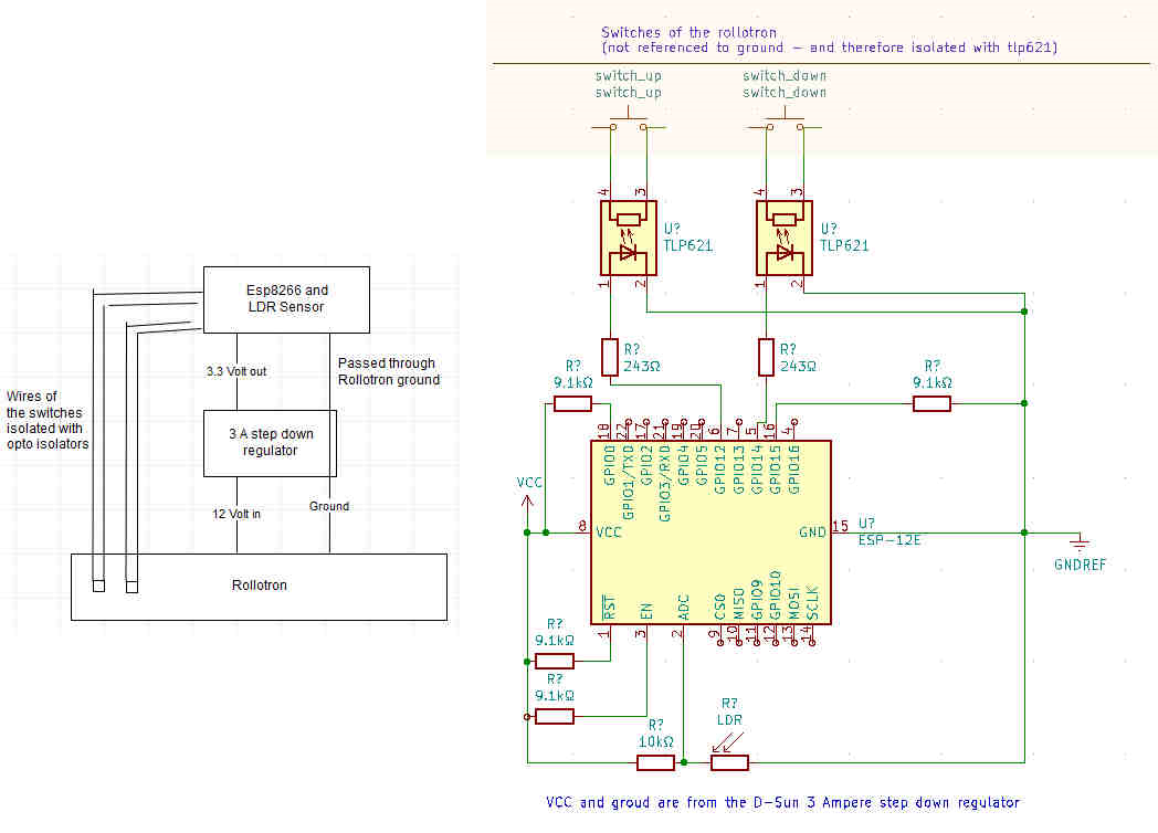
Here is the module:
Used components:
- GPIO12: TLP621 opto isolator with 243Ω resistor on the anode for the up button
- GPIO14: TLP621 opto isolator with 243Ω resistor on the anode for the down button
- 9.1kΩ pull-up resistors on RESET, CH_PD and FLASH
- 9.1kΩ pull-down resistor on MTD0 (GPIO15)
- The ADC pin has a LDR with 10k resistor as voltage devidor (on 3.3 vcc)
Does anyone have further ideas how to solve or troubleshoot this issue?


