3
\$\begingroup\$

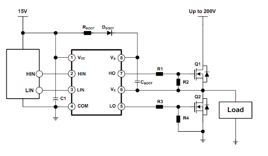
I was reading this bootstrap circuit for a N CH MOSFETS and I am finally starting to understand how a bootstrap circuit for MOSFETS work. The one part I am confused about is how the MOSFET stays turned on once the source gets connected to the main power supply.

According to this circuit, the bootstrap capacitor is brought to a voltage of VCC which is then connected to gate which turns on the MOSFET, but when this happens the main power supply, which is much greaterthan VCC, will be connected to the source which should then make the source voltage greater than the VCC voltage of the bootstrap capacitor connected to gate. How is it possible to connect the source to a higher voltage than the bootstrap capacitor without the MOSFET turning off?

\$\endgroup\$
1
  • \$\begingroup\$ One side of the bootstrap capacitor is permanently connected to the source of the high side FET, the other side of the charged bootstrap capacitor is connected to the gate by the gate driver. So the capacitor is across source-gate. As source voltage rises, the capacitor "rides up" along with it, keeping the gate voltage at "source voltage + bootstrap capacitor voltage". \$\endgroup\$ Commented Aug 10, 2022 at 3:40

2 Answers 2

1
\$\begingroup\$

Look at the schematic from the question you linked:

enter image description here

Note that one side of the capacitor is connected to the source of the upper MOSFET. When Q2 turn on, Cboot charges to a diode drop below the 15V supply through Dboot. When Q2 turns off and Q1 turns on, Cboot rides on the switch node or source of Q1 always staying about 14.3 V above the source. Dboot will be reverse biased as soon as the switch node rises above ~15V, so Cboot will only be discharged by the gate charge of the FET, the Iq of the driver, and the current through R2. The ON time should be short enough so that Cboot doesn't discharge below the desired minimum Vgs before the next off time.

\$\endgroup\$
1
\$\begingroup\$

The bottom of the bootstrap capacitor is connected to the source, and the top is connected to VCC via a diode. When the MOSFET is off and the source is at GND, the capacitors will be charged.

Next, the top of the capacitor is connected (by a small transistor switch) to get MOSFETs gate. This drives the gate to the VCC level (say 5 V). Now the MOSFET has a fixed VGS of 5 V and is turning on. Since VGS is fixed (by the capacitor), both gate and source will rise. The gate will eventually be 'pumped' 5V above the supply and will remain there until the capacitor's charge leaks away or is discharged.

\$\endgroup\$
1
  • \$\begingroup\$ It may be important to say that the gate charge must be discharged to turn off the MOSFET, and may require fairly high current if gate capacitance is large and turn-off time needs to be fast. \$\endgroup\$
    – PStechPaul
    Commented Aug 10, 2022 at 5:24

Your Answer

By clicking “Post Your Answer”, you agree to our terms of service and acknowledge you have read our privacy policy.

Not the answer you're looking for? Browse other questions tagged or ask your own question.