2
\$\begingroup\$

I need a circuit that compares two periodic pulse signals and outputs a low or high when the frequency of one is higher than the other.

The two input signals are coming from CMOS 74HC devices. The width of the pulses is fixed and in the ns range (so duty cycle is not variable so to speak), and the frequencies of either of the inputs are anywhere from 20 Hz-20 kHz (audio range).

I prefer to do this entirely with 74HC devices and not some specialized IC if possible. Maybe some such circuit already exists and I don't know to call it?

\$\endgroup\$
5
  • 2
    \$\begingroup\$ Two frequency-to-voltage converters and a regular old comparator? \$\endgroup\$
    – Hearth
    Commented Aug 12, 2022 at 4:33
  • \$\begingroup\$ What signals are they? Logic pulses, square waves, etc? What is the frequency range? You could build a phase frequency detector or see if an existing PLL chip has suitable one built-in. \$\endgroup\$
    – Justme
    Commented Aug 12, 2022 at 4:49
  • \$\begingroup\$ 74HC doesn't do "pulses in the ns range" very well. What pulse repetition frequencies are you looking to compare, and what's the pulse width? Are the pulses fixed width, or is the duty cycle constant, or is the duty cycle variable and unrelated to frequency? Be specific. \$\endgroup\$ Commented Aug 12, 2022 at 5:03
  • \$\begingroup\$ @Kubahasn'tforgottenMonica edited the post, thanks \$\endgroup\$
    – Jon
    Commented Aug 12, 2022 at 5:20
  • \$\begingroup\$ @Jon Your dynamic range is three orders of magnitude. And you haven't mentioned anything about your hysteresis specs, either. If you don't have any, you may find the output quite jittery at times and entirely dependent on the circuit design. There isn't a single name for this, much as you may wish it, as there are many alternative approaches to something like this... depending. (Even given your limitations to 74HC devices.) \$\endgroup\$
    – jonk
    Commented Aug 12, 2022 at 5:46

6 Answers 6

1
\$\begingroup\$

The 74HC4046 is a phase locked loop IC with several phase detectors. Phase detector 1 (PD1) is an XOR gate that provides an output of 0 to Vcc for phase difference of 0-180 degrees. PC2 uses flip-flops and a counter that allows for a variable output over a lock range of +/- 1 kHz to 4 kHz. See the application sheet for more information. For a wider range, you might use two frequency-to-voltage devices and a comparator.

\$\endgroup\$
1
\$\begingroup\$

One option is to feed to the pulses to a resistor in series with a capacitor (each of the signals to its own R-C block). The R-C block would act as a frequency average. If the frequency is greater, the Capacitor would go up in voltage, and vice versa (assuming constant amplitude). You'd first need to feed the pulses to a monostable vibrator which would output to the R-C blocks (two monostables - one for each pulse stream). The monostables would output a constant width pulse for each positive voltage pulse (otherwise, without a monostable, the lower frequency pulses would be wider and higher frequency narrower, such that the capacitor would have roughly the same voltage regardless of frequency, if the frequency range is narrow).

Finally the two capacitors can be fed to an Op Amp, which would compare their voltages, telling you which pulse stream has a higher frequency.

This is done in a type of FM demodulation (monostable FM demodulation) to convert frequency into voltage, except they don't have two streams, and they don't have a comparator at the end to see which comes higher.

Two 555 timers can be configured as your monostables.

The values of the R-C can be determined by experimentation (Falstad Circuit Simulator would be good for this). As a recap, the R-C come at the output of the monostables. And the monostables are fed with the original signals (one signal stream for each monostable 555).

\$\endgroup\$
1
\$\begingroup\$

Consider two clock signals, clk A and clk B.

Looking between two successive rising edges of clk A (the period), if we ever two or more rising edges of clk B then clk B is running faster.

If we don’t see any clk B edges then clk A is faster.

If we see exactly one clk B edge then they’re sort of close and we have to keep looking until we see a doubled or missing clk B.

In the simple circuit below we’re trying to detect two clocks in a row before the other clock has a chance to reset the first flop via an asynchronous reset.

Any time a clock arrives it sets its first flop and resets the other clock’s first flop.

If the 2nd flop ever triggers then that clock is faster and it sets or resets the final flop, latching the result for us to view with LEDs.

It is impervious to pulse width variation since it only looks at positive edges.
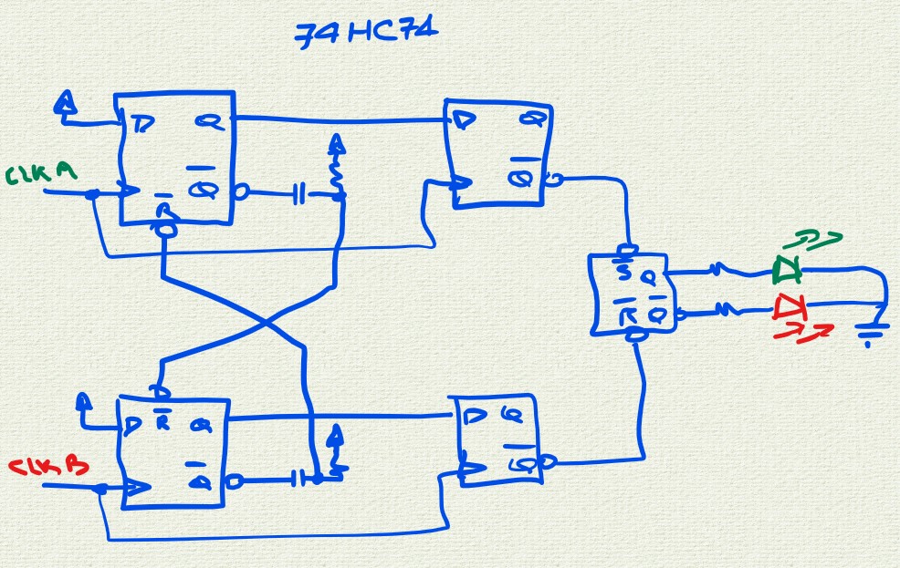
enter image description here

This algorithm could be implemented any number of ways but OP asked for 7CHC solution. Regardless of implementation, this algorithm has advantages over brute force "measure frequency or period and compare results" schemes because it directly determines "faster or slower?" without limitations of measuring period which both digital and analog solutions have trouble with at frequency extremes.

\$\endgroup\$
0
\$\begingroup\$

If pulses are narrow, you can use them to reset 2 sawtooth waves.
Sample the peak voltage.
The lowest is the most high frequency.

NB: you can replace the 2 sawtooths with two counters...
Just "compare" results.

When the frequencies are "near", probably another approach would be used to "confirm".

\$\endgroup\$
0
\$\begingroup\$

The minimum frequency of 20Hz is quite low and will force a long settling time if analog solutions based on frequency, like a phase frequency detector, are used. Anything that averages over several periods to measure frequency will take a while to settle at 20Hz.

So it would be more accurate to measure period instead of frequency. The maximum frequency of 20kHz is also quite low, which means this doesn't need any fast circuit.

The simplest way would be to use a micro with both signals going into the capture input of two timer/counter units. This can be used to measure the period accurately, then the micro can compare and output the desired value.

It would probably be possible to use a period to frequency converter, but the low frequency risks making the passive component values a bit impractical.

\$\endgroup\$
0
\$\begingroup\$

Here is another circuit using "only" digital circuits ... to be checked at all frequencies.

The idea is to convert the "period" to a voltage.
Thus I draw a digital circuit that could be used.
Something as this.

enter image description here

Configuration of swapped frequencies ...

enter image description here

\$\endgroup\$

Your Answer

By clicking “Post Your Answer”, you agree to our terms of service and acknowledge you have read our privacy policy.

Not the answer you're looking for? Browse other questions tagged or ask your own question.