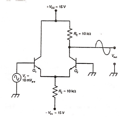
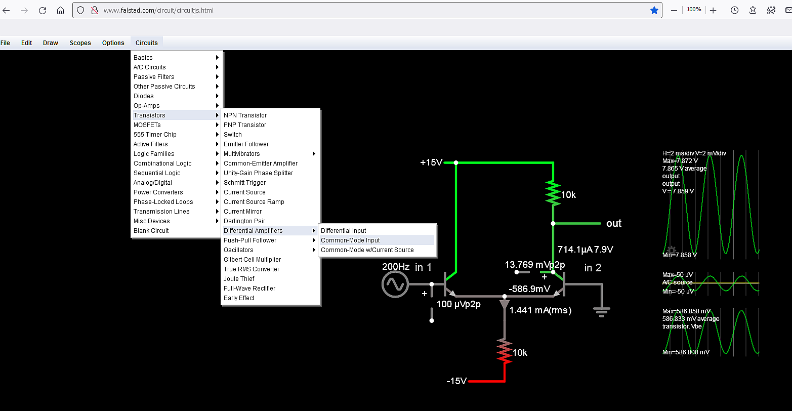
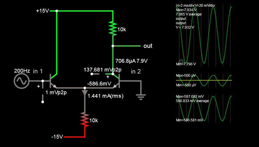
Well, you could analyse the circuit to find the quiescent current in both BJTs. It's going to be about 0.75 mA in each. Can you see that?
With a current of 0.75 mA, a BJT's internal emitter resistance (\$r_E\$) will be approximately 35 Ω. Here's a google example of that formula (red stuff by me): -
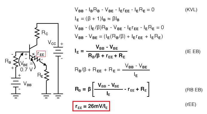
Image from here and, this degenerates aka causes negative feedback. I'm sure Mark Hughes won't mind me stealing his circuit and marking it up!
So, with 0.75 mA flowing, \$r_E\$ = 35 Ω. Given that there are two emitters joined (and ignoring the very small effects from \$R_E\$), the gain can be estimated as being \$R_C/70\$ = approximately 143.
Hence, for 10 mV p-p in, you would get 1.43 V p-p out.
This output voltage is small enough not to significantly affect the 26 mV/IE calculation done earlier.
Sanity check using a simulator: -
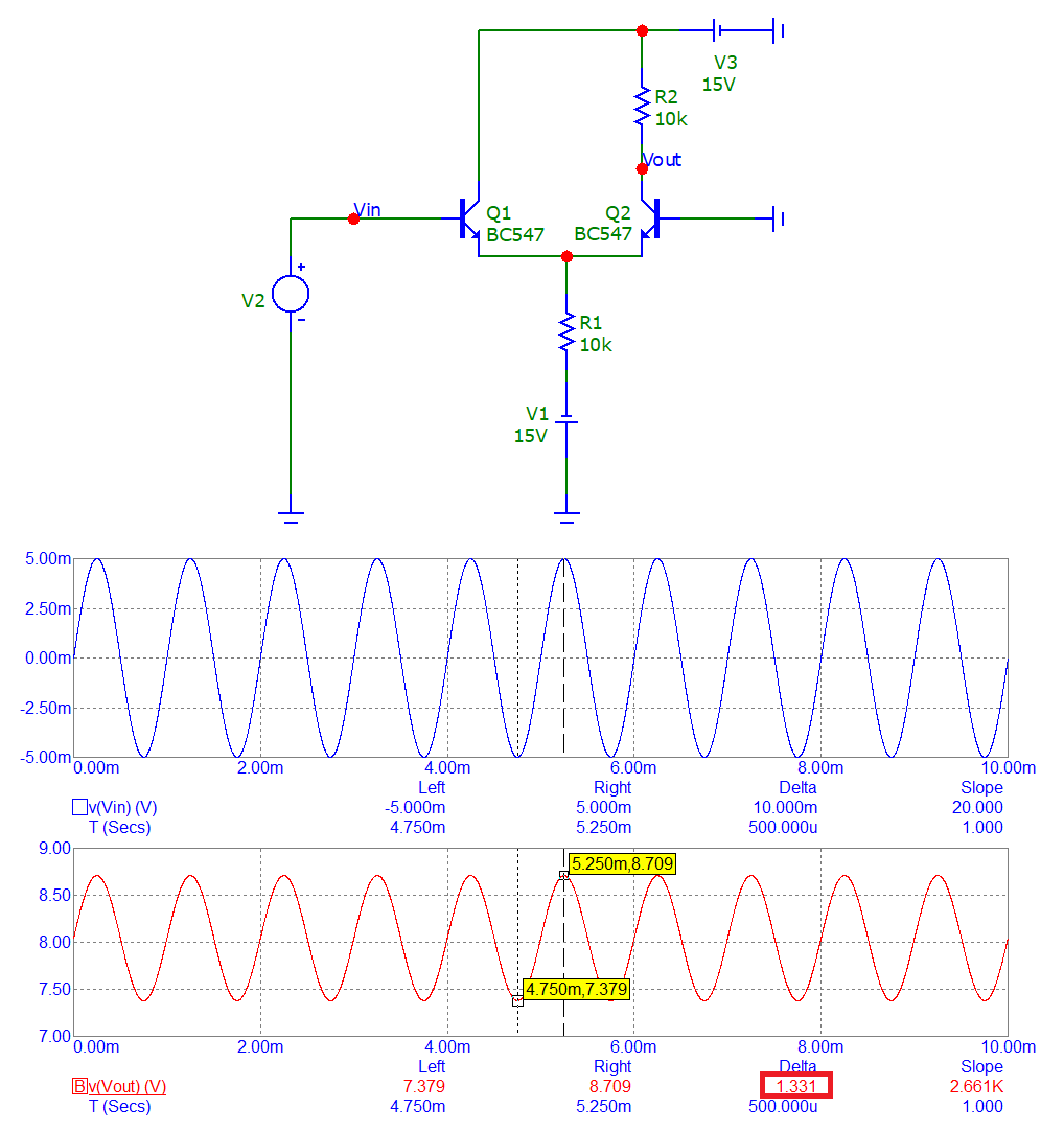
The input signal (in blue) is 10 mV p-p and, the output signal (in red) is 1.331 volts p-p. That's a close result for a simple BJT circuit.

