2
\$\begingroup\$

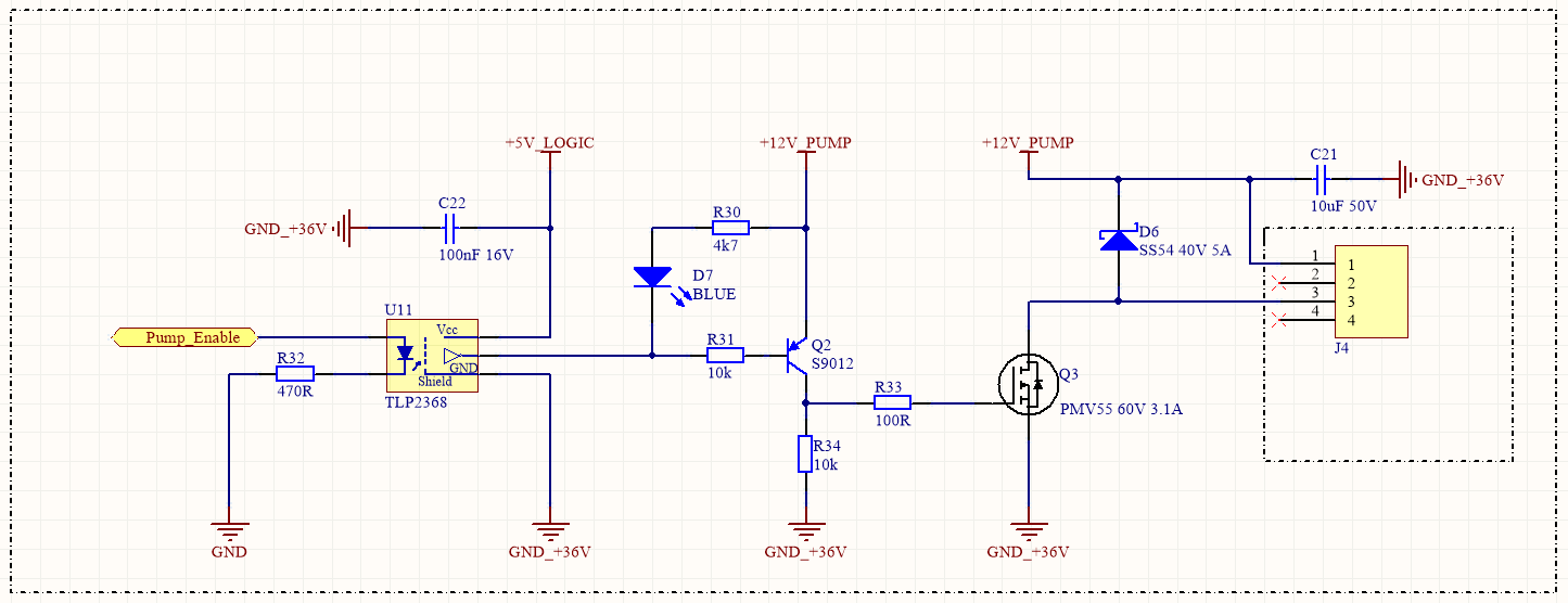
I have a problem with a circuit as shown below.

Circuit

I want to drive a pump with the Pump_enable signal but no metter how is this signal state - high or low, the Q3 and Q2 tranistors are always on and the pump is always running.

When I remove the optocoupler from the circuit and simply connect the Q2 base to the ground the pump is running and when I connect it to the +12V its stop.

I am not sure what I have done wrong, I appreciate for any advice and materials to learn.

I am also not sure about the placement of the blue LED diode in this circuit, the purpouse was to sygnalize when the pump is ON. It works fine when I pull Pump_Enable signal high, the LED turns on there is no difference in transistors work. Without D7 and R30 there is no difference.

\$\endgroup\$

2 Answers 2

2
\$\begingroup\$

I appreciate for any advice

The opto-isolator needs to produce an output signal that is closer to 12 volts to turn off the pump. At the moment it's maximum output level is 5 volts and, Q2 will still be turned on and the pump will continue running.

If you choose a logic-level MOSFET you might be able to use the opto circuit to directly drive the MOSFETs gate and rid yourself of the pesky Q2 circuit.

\$\endgroup\$
0
2
\$\begingroup\$

Issue: You're using the wrong optocoupler. It's not made to block 12V so you have a current flowing from 12V trough collector-base of Q2 which makes it conduct which makes the FET switch on.

Solution: Use another Optocoupler with a realy Open collector output that can handle at least 12V.

\$\endgroup\$
2
  • 1
    \$\begingroup\$ You're right. I've switched the optocupler to LTV-357T and now it is working well. I've also add a pull up resistor on the Q2 base to be sure it is closed properly. But I was wonder to control this pump with a PWM signal apllied on a optocoupler input that is why I had picked the previous high-speed optoisolator, and I am not sure it will work now if I provide Pump_enable signal as PWM? \$\endgroup\$
    – Lime7
    Commented Sep 15, 2022 at 14:21
  • \$\begingroup\$ It depends on what frequency PWM you're using. But for the ususal PWM freuqencies of a few kHz at most, Optecouplers ar normally plenty fast enough. It all depends on how much you drive the output transistor into saturation, Ic and Vce. But acording to the datasheet, the new OptoCoupler has a worst case response time of 18us. \$\endgroup\$
    – kruemi
    Commented Sep 16, 2022 at 6:13

Your Answer

By clicking “Post Your Answer”, you agree to our terms of service and acknowledge you have read our privacy policy.

Not the answer you're looking for? Browse other questions tagged or ask your own question.