2
\$\begingroup\$

I am learning about op-amps from this tutorial from Circuitbread.com on YouTube.

The instructor states around the 9:30 mark (video clip):

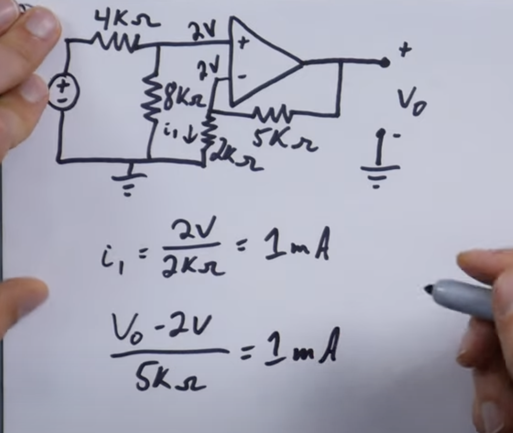
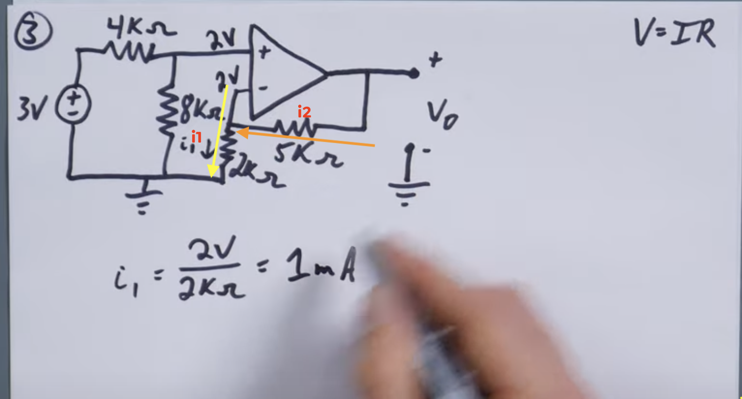
Because we have 1 mA (through i1) we know we have 1 mA (through i2).

enter image description here

How does the instructor know/assume that the current would be the same across these resistors?

When I calulate the current I get different values:

$$i_1 = \frac{2\mathrm{\ V}}{2 \mathrm{\ k\Omega}} = 1\mathrm{\ mA}\\ i_2 = \frac{2\mathrm{\ V}}{5\mathrm{\ k\Omega}} = 0.4\mathrm{\ mA}$$

Later in the video, they even show the formula:

$$\frac{v_0-2\mathrm{\ V}}{5 \mathrm{\ k\Omega}}= 1 \mathrm{\ mA}$$

enter image description here

Is this a mistake or am I misunderstanding something?

Update

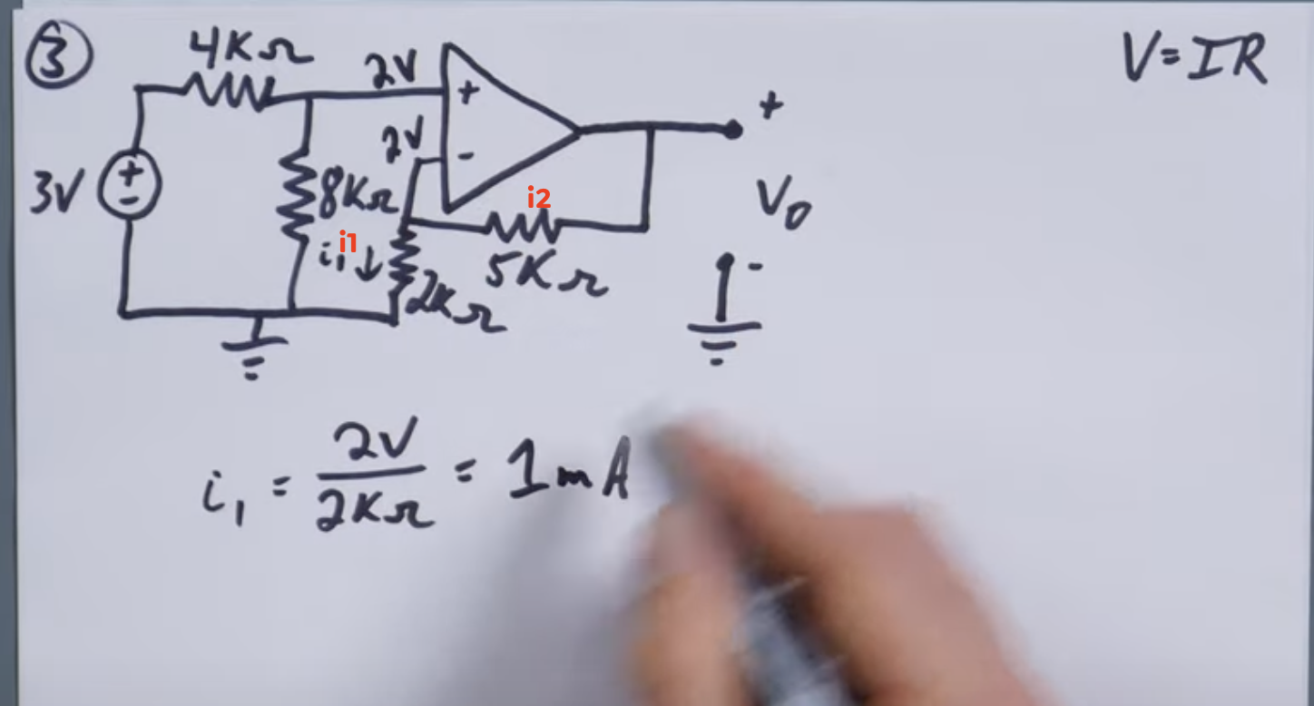
I think I've identified my incorrect assumption. I was thinking of the current traveling through the yellow line, instead of through the orange line. If the current is traveling the orange line, it makes sense that both i1 and i2 would be seeing the same current since they are in series.

enter image description here

\$\endgroup\$
7
  • 6
    \$\begingroup\$ To intuit the answer: ask yourself how much current is flowing in or out of the negative terminal of the opamp. \$\endgroup\$
    – Bryan
    Commented Oct 31, 2022 at 4:39
  • 5
    \$\begingroup\$ Current is not across, current is through. Remember all currents into a node add up to zero (when consistent direction is used) by Kirchhoff's Current Law. \$\endgroup\$ Commented Oct 31, 2022 at 4:46
  • 2
    \$\begingroup\$ Why do you say there's 2 V across the 5 kΩ resistor? There's not. \$\endgroup\$
    – Hearth
    Commented Oct 31, 2022 at 4:58
  • \$\begingroup\$ One of the assumptions of op-amp circuits (given that there is negative feedback) is that no current flows into the op-amp input. Therefore all the charges which flow into the 5k resistor have no choice but to continue on through the 2k resistor. They are not allowed to take the alternate path into the op-amp. This is what the person means when they say that the currents must be the same. \$\endgroup\$
    – user57037
    Commented Oct 31, 2022 at 7:27
  • \$\begingroup\$ If it turns out that the current is negative, then you can just reverse the direction: all charges which flow into the 2 k resistor have no choice but to carry on through the 5 k resistor. \$\endgroup\$
    – user57037
    Commented Oct 31, 2022 at 7:28

5 Answers 5

9
\$\begingroup\$

Looking at the datasheet of a random opamp (LM358)

enter image description here

Input bias current is the current that flows into the input pins (positive and negative). It's pretty low, 50nA typical, 0.5µA maximum over temperature.

So the usual method is to assume input current is negligible and calculate gain accordingly. You have 1mA through the resistors, even with the worst case input bias current of 500nA, that's only 0.05%. It doesn't change much with input voltage as long as it is within the allowed input common mode range, so it has very little influence on the gain.

Neglecting opamp input current, the two resistors appear in series so the same current flows through both. This means they form a voltage divider, and voltage at the opamp negative input is 2k/(2k+5k) times output voltage, that's your feedback ratio.

After you have calculated the gain, you can now bring back the opamp's input bias and offset current and calculate how much offset voltage they will cause at the output.

\$\endgroup\$
0
3
\$\begingroup\$

The assumption that the currents are the same follows from a few other assumptions that you have perhaps not been exposed to yet. First of all, the current flowing into the op-amp inputs is zero (or negligible, let us say).

Second of all, charges cannot be stored in circuit elements such as op-amps, resistors, capacitors, inductors, etc. Whenever a charge enters, another one must exit somewhere else. This is a fundamental of circuit analysis.

These two taken together mean that i1 and i2 are equal.

You wrote the equation i2 = 5V / 2k. I don't see where that equation came from. It does not seem to be a correct equation for this system.

The equation from the video appears to be correct. When you solve for Vo you will get 7 V. This means that i2 = (7-2) / 5k = 1 mA.

\$\endgroup\$
1
  • 1
    \$\begingroup\$ The second rule is also called Kirchhoff's Current Law. \$\endgroup\$ Commented Oct 31, 2022 at 14:34
2
\$\begingroup\$

For these types of calculations you usually assume an ideal operational amplifier. The current into any of the two inputs of an ideal operational amplifier is always zero.

In reality the currents into the inputs aren't zero (see "input bias current" in the respective datasheet). It depends on the type of amplifier and the application whether these currents are relevant or negligible.

\$\endgroup\$
0
\$\begingroup\$

The 7V output minus the 2V at the inverting input is 5V that is across the 5k resistor causing a current of 1mA.

\$\endgroup\$
0
\$\begingroup\$

Internal input resistance of a practical op amp is very high and hence very low current flows that can be neglected ideally R=infinite and Ii = 0.

\$\endgroup\$

Your Answer

By clicking “Post Your Answer”, you agree to our terms of service and acknowledge you have read our privacy policy.

Not the answer you're looking for? Browse other questions tagged or ask your own question.