6
\$\begingroup\$

I have a PCB that has only one footprint for decoupling capacitors per opamp supply rail. I'd like to add another capacitor in parallel and thought of "stacking" two 0.1uF and 10uF ceramic capacitors (1206). I've tested the stacking method and the connection seems good when measured with a multimeter. However, I only have a single PCB and thought I would ask her for the pros and cons of doing such a hack job first.

What are the pros and cons of stacking capacitors for supply rail decoupling?

Is there any practical difference between stacking capacitors on a single footprint vs multiple footprints in parallel?

\$\endgroup\$
1
  • \$\begingroup\$ If very concerned about vibration, add a 30ga wire to both soldered edges as reinforcement. \$\endgroup\$
    – rdtsc
    Commented Nov 9, 2022 at 20:37

6 Answers 6

19
\$\begingroup\$

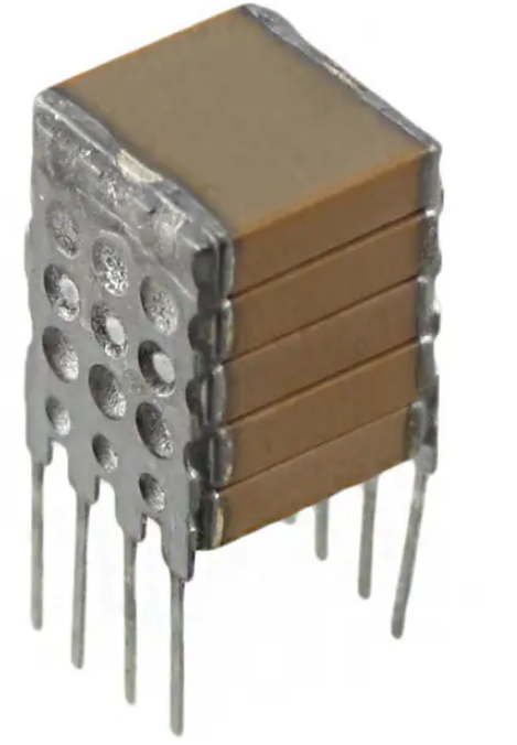
You can do this. You can even buy capacitors pre-stacked for your convenience (albeit at an eye-watering cost): photo from Digi-Key for Kyocera P/N SMX43C106KAN360 - this is done to get very high values for the current state of MLCC technology, not to combine different values.

enter image description here

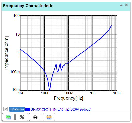
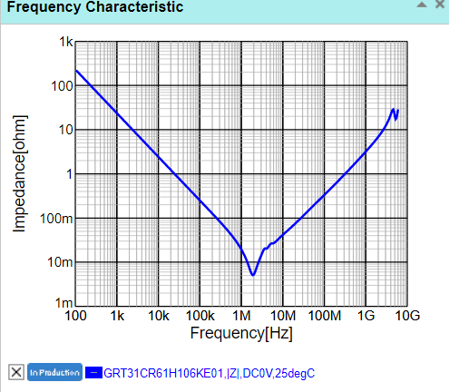
Ideally put the 0.1uF on the bottom since it will (in theory anyway) have lower parasitics at high frequency. But check the detailed data for the caps- it's possible the 10uF alone is more than adequate and the 0.1uF won't be doing much of value. Unless your op-amp is a very high frequency type I would expect that to be the case, and even then it may not matter much.

For example, look at these two Murata parts:

0.1uF:

enter image description here

10uF:

enter image description here

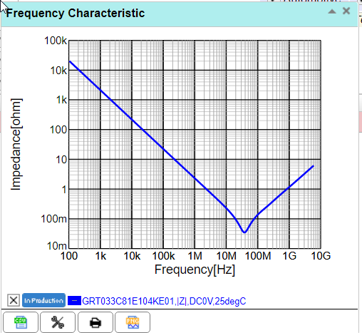
You can see that adding the 100nF in parallel does not really do much at any frequency between 100Hz and several GHz. Combining an 0201 100nF part with a 1206 10uF might make sense in some cases (but of course you're not going to be able to do that vertically, especially with the 0201 on the bottom with the shortest possible paths- mostly it makes sense because the cap is tiny and you can get it really close to the pins):

enter image description here

\$\endgroup\$
2
  • \$\begingroup\$ The way those stacked capacitors have leads also makes them significantly more robust against mechanical vibration and boardflex, allowing them to make them using substantially larger (in terms of physical size) capacitors, which also increases capacitance. I've never actually used one, but the dimensions in some datasheets look completely ridiculous for ceramic capacitors. \$\endgroup\$
    – Hearth
    Commented Nov 11, 2022 at 5:26
  • \$\begingroup\$ Another example of pre-stacked capacitors. TDK p/n CKG57NX7R2A106M500JJ. Fewer capacitors in a stack, much cheaper, pick&place-friendly. I'm guessing that the main use case for the pre-made capacitor statcks is filter caps in switch-mode power supplies. \$\endgroup\$ Commented Nov 11, 2022 at 22:45
10
\$\begingroup\$

Stacking SMD MLCC capacitors is perfectly fine electrically. If the capacitors don't get too tall, it should also be fine mechanically, but vibrations might become a problem.

Stacked capacitors can be put closer to the IC and therefore have less parasitic inductance than ones placed on individual footprints. In that way, it's electrically better to stack them than to place them next to each other.

The reason why this isn't done commercially is that it can't be mass-manufactured on pick-and-place machines. However, you can buy stacked MLCCs that have been welded together as a single SMD part. If you manufacture your boards by hand, there's nothing preventing you from stacking MLCCs.

\$\endgroup\$
1
  • 6
    \$\begingroup\$ I would argue that stacked capacitors have more parasitic inductance since you are increasing the current loop area in the vertical dimension. It might not be as much of a difference. \$\endgroup\$ Commented Nov 9, 2022 at 20:37
8
\$\begingroup\$

Stacking is permitted for all three classes of electronic assemblies (toy through critical-use devices) under IPC-A-610 section 8.3.2.9.3. The top component must satisfy the same soldering criteria as the bottom component but with the bottom component's terminals as the pads for the top component.

\$\endgroup\$
2
\$\begingroup\$

What are the pros and cons of stacking capacitors for supply rail decoupling?

The parasitics from vias (or via) that are used is the main difference. In high frequency applications this can make a difference because the vias usually limit performance. It's better to have a set of vias for each capacitor. The other difference is the small amount of inductance of the metal of the capacitor below that the current of the capacitor above would run through, so it would be better to place the smaller capacitor on the bottom.

Sometimes stacking is the only option, especially if you don't want to change the PCB or for testing purposes stacking can be good.

If it's for an opamp supply and the bandwidth is low (like below 1MHz) its likely that it wouldn't make a difference.

\$\endgroup\$
2
  • \$\begingroup\$ OP didn't mention vias. \$\endgroup\$
    – TypeIA
    Commented Nov 9, 2022 at 20:53
  • 5
    \$\begingroup\$ Most capacitor designs use at least one via to get to the power plane \$\endgroup\$
    – Voltage Spike
    Commented Nov 9, 2022 at 20:56
1
\$\begingroup\$

One issue is that the 10uF is likely larger and best suited for going on the bottom, but electricall the 0.1uF should be on the bottom. Your meter won't detect this difference unless you place the cap on a test PCB and measure an LCR meter than can measure capacitance at the decoupling frequencies (10MHz and up).

The a 10uF is quite small though so it may not add too much parasitic inductance to the 0.1uF cap so much.

\$\endgroup\$
1
\$\begingroup\$

Smaller capacitance values aren't much better at high frequencies unless they are physically smaller. Dielectric isn't nearly as important as physical size. So, a stack of 1206 capacitors with different values is not much better than one capacitor of the largest value. Better to put an 0603 or 0402 next to it.

\$\endgroup\$

Your Answer

By clicking “Post Your Answer”, you agree to our terms of service and acknowledge you have read our privacy policy.

Not the answer you're looking for? Browse other questions tagged or ask your own question.