2
\$\begingroup\$

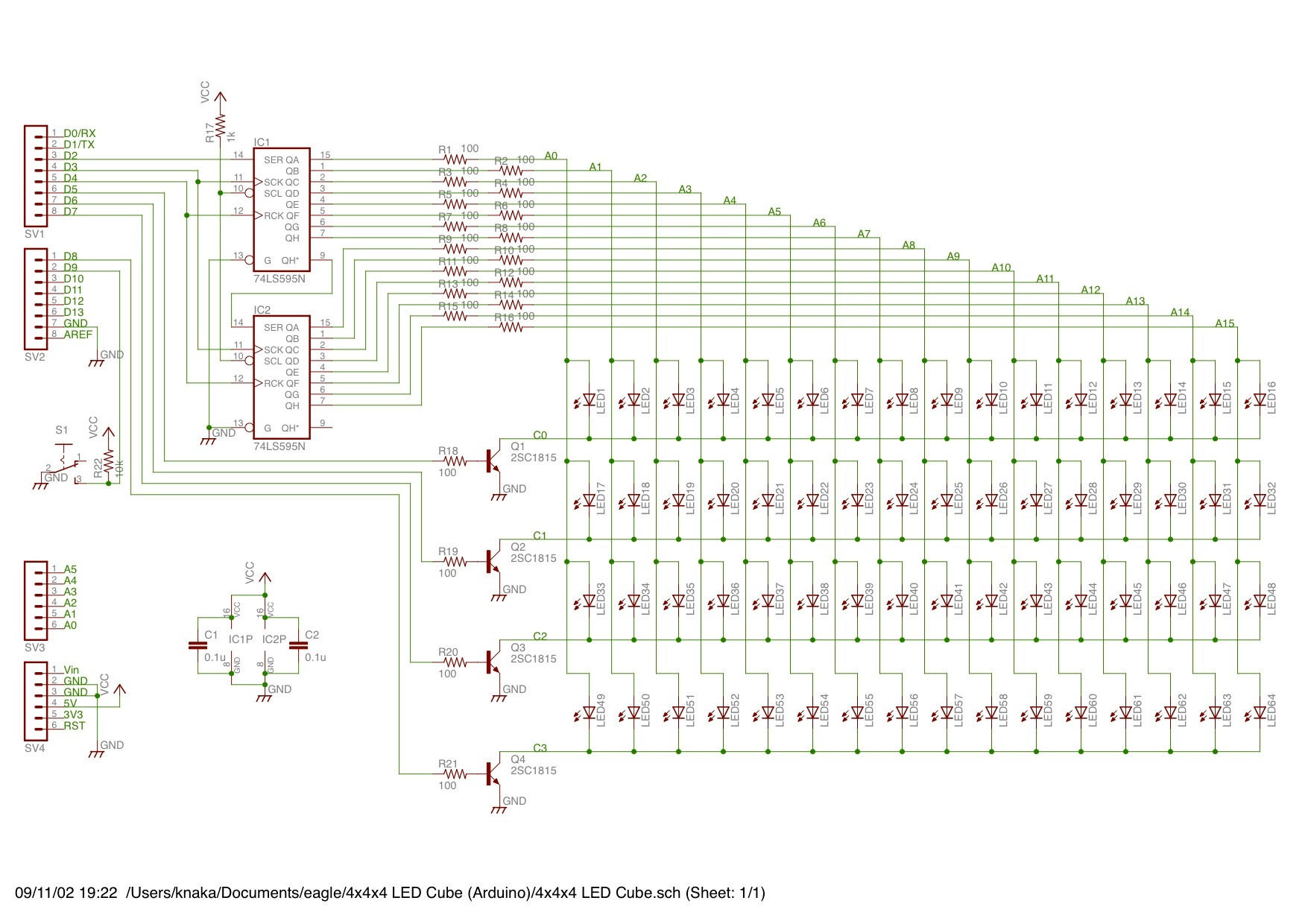
TOday, I have built an LED cube. I put it all together, arduino, mess of wires and all, and it doesn't work. Fiddling with it a little bit, I find that if I short certain wires to ground, the LED's work. Therefore, I think that it is the transistors controlling the pathway to ground that are the problem. This is the transistor circuit:

enter image description here

T1
EBC
||+Led Cathode |Arduino Pin Ground

T1 is a NPN transistor, EBC are Emitter, Collector, and Base. Base to arduino pin, Emitter to Circuit ground, and Collector to Led Cathode. What I believe should happen is when I send HIGH to the base of the transistor, the LED cathode and the Circuit Ground should be connected. However, this is not working. Is there anything I'm doing wrong?

\$\endgroup\$
9
  • 2
    \$\begingroup\$ We need a schematic. \$\endgroup\$
    – Matt Young
    Commented Apr 7, 2013 at 19:25
  • \$\begingroup\$ All right, give me a minute. \$\endgroup\$ Commented Apr 7, 2013 at 19:26
  • 2
    \$\begingroup\$ There exist single IC's which will drive 64 LED's. You just talk to them through some serial protocol like \$I^2C\$ and they take care of it. No external components like transistors needed. So you are solving this LED lighting problem in an unnecessarily complicated way. \$\endgroup\$
    – Kaz
    Commented Apr 7, 2013 at 20:22
  • 3
    \$\begingroup\$ Useless question title! \$\endgroup\$ Commented Apr 7, 2013 at 20:31
  • 2
    \$\begingroup\$ I prefer FETs over Bjt's they work better for me \$\endgroup\$
    – skyler
    Commented Apr 7, 2013 at 21:06

2 Answers 2

4
\$\begingroup\$

If what you're doing is putting together an assembly and then testing to see if it works, yes, you're doing something wrong. Do your build in a left-to-right way, checking what's going on at each stage, and you should be able to see what/if you're doing anything wrong. Debugging this sort of stuff is a valuable skill, and you'll never learn it if you don't try it.

Especially after you've failed at the build-the-whole-shebang-at-once style, it's time to take on your project in a modular way.

Start by making sure your powers, grounds, etc., are what they should be and what you think they are.

Then, use an input to mimic your TTL, ONE transistor, and ONE LED. When you've got that working, hook it up to your 74ls. If that's still working, now try to add the additional LEDs.

This is PARTICULARY difficult when there's a microcontroller and firmware in between you and your electronics. In that case, there are some interesting ways to proceed. The first is to not bother with the microcontroller until you've got the external hardware working. Among the debugging benefits, this will FORCE you to understand your external hardware and it's interaction with the firmware. Frankly, this is a level of understanding I think many beginning with the Arduino platform just skip. That's OK, but they'll need to pick it up later.

An alternative approach is to build yourself a test platform with the microcontroller, which will let you diddle around with what you need to diddle around with easily. Experienced embedded hardware folks would refer to this as a SANDBOX. Designing your sandbox properly for a project is almost a full project all by itself, but doing it right will save you time and effort in the long run.

Once your system is working standalone or with your sandbox, then migrate to the final version.

\$\endgroup\$
2
\$\begingroup\$

Your circuit looks correctly connected, but the currents you are apparently asking for are suspicious. You didn't say what Vcc is but apparently 5 V given the 74LS logic. Let's say the LEDs drop 2.1 V each (about right for green, red would be lower) and you expect the cathode transistors to get down to 200 mV when saturated, that leaves 2.7 V accross the LED resistors. 2.7 V / 100 Ω = 27 mA. That's bad if you are using ordinary 20 mA LEDs.

That also adds up to a lot of current for the trasistors to sink. There are 16 LEDs on each transistor, for a total of 430 mA. I didn't look up your transistors, but let's say the minimum guaranteed gain at 430 mA is 40. That means each needs 11 mA base current. That could be a lot for whatever is driving the Dx pins. What is the maximum source current of those digital outputs? However, you are actually asking them to source much more than that. Figure 700 mV for the B-E drop, so 4.3 V accross each base resistor. That's 43 mA you are asking of your digital outputs! How did you ever come up with 100 Ω base resistors?

A even bigger problem is that you are expecting the 74LS gate output to source the full current for each LED. Are you really sure they are rated for 27 mA source capability, or even 20 mA if you adjust the resistors for that? That would be surprisingly high.

However, most likely these things would make the LEDs light dimly, not prevent them from lighting at all. Test this board out by itself before connecting it up to whatever is driving the Dx lines. You should be able to test individual rows and colums. Once that is working, the rest is firmware. Check with a scope to make sure the firmware is generating the correct waveforms.

\$\endgroup\$

Not the answer you're looking for? Browse other questions tagged or ask your own question.