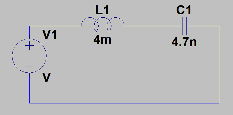
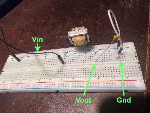
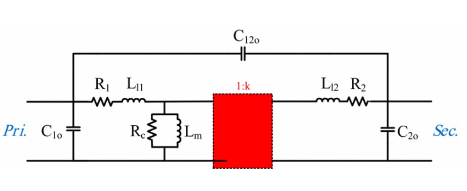
I am trying to get back into some electrical engineering basics, and had a quick question regarding an unexpected output I am seeing. I am trying to learn about RLC circuits again, and wanted to build a quick circuits with some parts that I had at my disposal. I found a random unmarked transformer, and used half of the transformer as a inductor, and found a small ceramic cap as well. The capacitor I believe is 4.7 nF and the inductance I measured to be around a couple of mH (around 4 mH), and I decided to slap them in series on a breadboard together.
I know that the rails of the breadboard may contribute some parasitic capacitances, and there is resistance in the wires I am using for these components which may affect the final Vout voltage (the voltage drop over my capacitor).
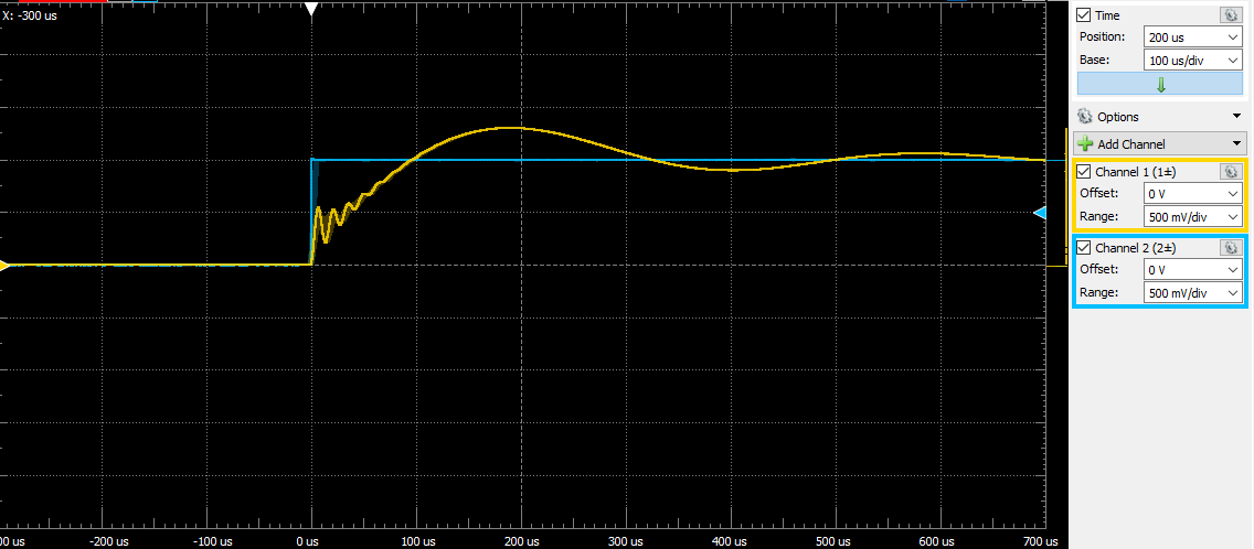
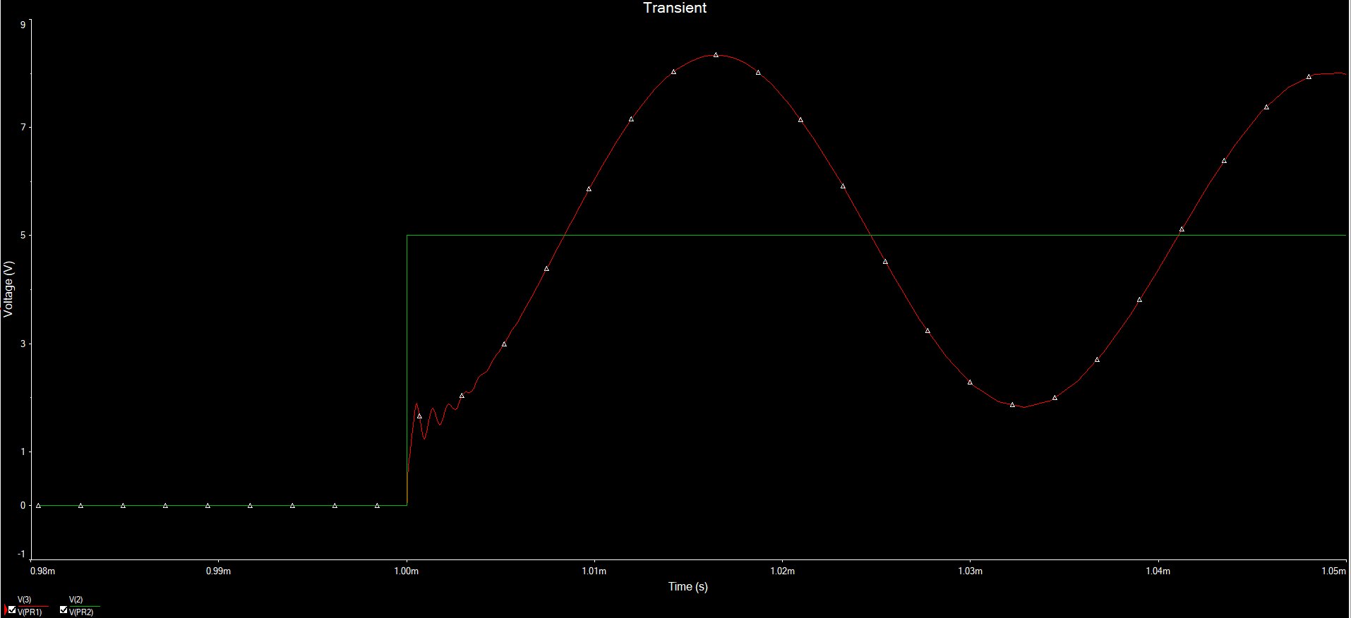
Anyways, when I feed in a step input voltage, and measure the voltage drop over my capacitor, I get something interesting. As shown in the picture, it looks like two decaying sinusoids (one initial high frequency burst and another larger sinusoid) overlaying one another, and was wondering why or how this may come into place? I asked myself "What kind of circuit would I need to create such that I would see this output voltage?" And I couldn't think of anything. This is more of an open-ended question, not really related to the specific setup I have, but just a general kind of question as to why this may happen in the real world. Thanks again!

