3
\$\begingroup\$

I am struggling to get an acknowledge from the MPU6050 using ESP32 with Arduino framework. I am unable to derive if the problem is hardware or firmware.

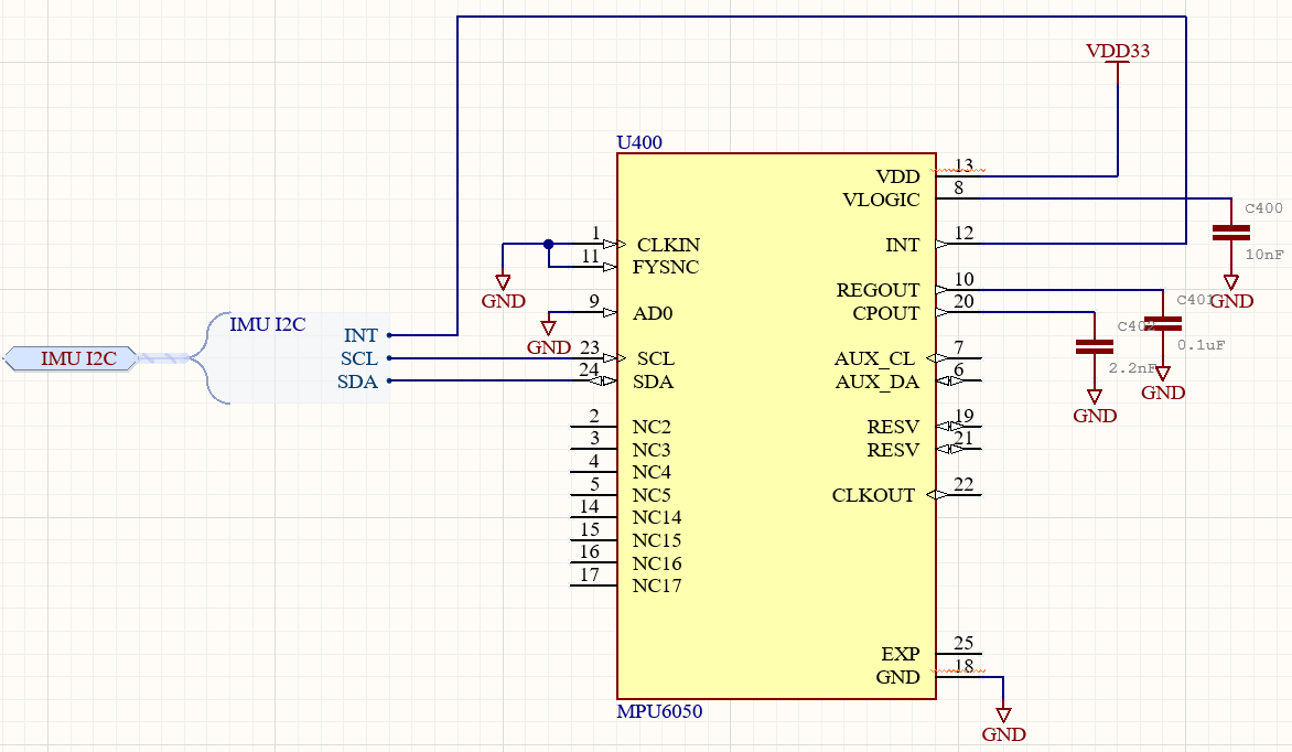
I have copied Sparkfun's breakout board schematic, setting the FSYNC, CLKIN and AD0 pins to GND and SDA, SCL and INT to GPIOs 25, 26 and 27 respectively (INT is unused/floating). I am using 2.7 kΩ pull-ups for the I2C lines.

enter image description here

I am using the following code to test the I2C comms:

#include <Wire.h>
 
#define I2C_SDA 25
#define I2C_SCL 26

void setup() {
  Wire.setClock(100000UL);
  Wire.begin(I2C_SDA, I2C_SCL);
  delay(3000);
  Serial.begin(115200);
  Serial.println("\nI2C Scanner");
}
 
void loop() {
  byte error, address;
  int nDevices;
  Serial.println("Scanning...");
  nDevices = 0;
  for(address = 1; address < 127; address++ ) {
    Wire.beginTransmission(address);
    error = Wire.endTransmission();
    if (error == 0) {
      Serial.print("I2C device found at address 0x");
      if (address<16) {
        Serial.print("0");
      }
      Serial.println(address,HEX);
      nDevices++;
    }
    else if (error==4) {
      Serial.print("Unknow error at address 0x");
      if (address<16) {
        Serial.print("0");
      }
      Serial.println(address,HEX);
    }    
  }
  if (nDevices == 0) {
    Serial.println("No I2C devices found\n");
  }
  else {
    Serial.println("done\n");
  }
  delay(5000);          
}

I have probed the I2C line using a logic analyser. The code behaves as expected but I get no acknowledge. enter image description here

I have checked that the chip has power, lowered the speed from 200 kHz (default) to 100 kHz. I have tried using internal pull-ups on ESP32 instead of external. I have tried a different MPU6050 chip.

Any help diagnosing would be greatly appreciated.

\$\endgroup\$

1 Answer 1

2
\$\begingroup\$

Your schematic doesn't show any voltage source being connected to the MPU-6050 VLOGIC pin (just a decoupling capacitor connected there).

However the VLOGIC pin must be connected to a suitable voltage source, as it is used by the digital I/O part of the MPU-6050. Without that, the I2C I/O won't work (as you have seen).

Typically VLOGIC would be the I2C supply voltage, where 3.3 V and 1.8 V are common standards, depending on what else is on the I2C bus. In your case (although your schematic doesn't show everything) I think you are running the I2C bus at 3.3 V so just connect VLOGIC to your VDD for the MPU-6050.

From the MPU-6050 datasheet:

Explanation of VLOGIC input


On the Sparkfun schematic, you can see there is a net label VIO on the VLOGIC pin, which goes to the VIO terminal on the Sparkfun board's header. That must be connected to a suitable voltage. This seems to not be well-documented by Sparkfun (surprisingly for them) and this omission is mentioned in a review on their product page, which says:

I didn't see anything in the provided documentation from Sparkfun about having to connect the VIO line to a 3V3 source as an IO Reference voltage. This should be documented better.

\$\endgroup\$
2
  • 1
    \$\begingroup\$ Well spotted! I have connected VLOGIC to VDD and I2C communication now works! \$\endgroup\$ Commented Mar 15, 2023 at 14:54
  • \$\begingroup\$ @WillPowell - Great news :) \$\endgroup\$
    – SamGibson
    Commented Mar 15, 2023 at 14:55

Your Answer

By clicking “Post Your Answer”, you agree to our terms of service and acknowledge you have read our privacy policy.

Not the answer you're looking for? Browse other questions tagged or ask your own question.