2
\$\begingroup\$

I thought about this question when I read an interesting comment by @Simon Fitch in his answer.

In the complementary amplifier stage, in total there are three "pulling" elements - Q2 is a "pull-down" transistor when Vin is negative, Q1 is a "pull-up" transistor when Vin is positive, and the load RL is constantly a "pull-middle" resistor :-)
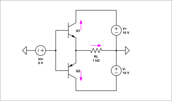
schematic

simulate this circuit – Schematic created using CircuitLab

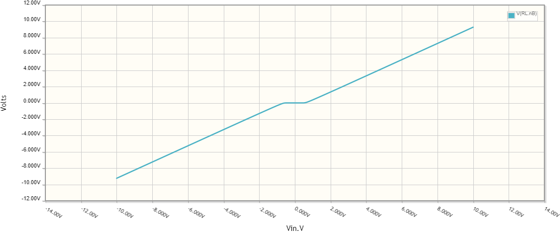
Push-pull graph

However, for some reason, this configuration is called "push-pull" stage. So there should also be a "pushing" element.

My question is, "What is it?"

\$\endgroup\$
13
  • 10
    \$\begingroup\$ Don't get too caught up on words. People use them, often, without precision unless they are writing for a very technical audience and have taken extra time to shape their words well for a formal setting. When speaking/writing colloquially and off-the-cuff, expect any and all abuses of words. That said, capacitors in DC-blocking settings are often nicely seen/viewed as pushing and pulling a driven node. Transistors, less so. \$\endgroup\$ Commented Apr 23, 2023 at 20:54
  • 2
    \$\begingroup\$ RL is a load resistance. \$\endgroup\$ Commented Apr 23, 2023 at 21:29
  • 1
    \$\begingroup\$ @Circuit In physics there are usually clear demarcations that nature shows us. For example, the concepts of solid, liquid, gas, and plasma arrive readily from phase diagrams about what nature shows us. Words tethered closely to physical nature, like that, carry meaning. On the other hand, words that describe internal mental states used to interpret the world through simplifying analogies may not always have such well-defined, objective, and clear demarcations and therefore much poorer robustness in my opinion. I prefer to see what nature says, than what some human says. More consistent. \$\endgroup\$ Commented Apr 23, 2023 at 21:33
  • 2
    \$\begingroup\$ @Circuitfantasist. Sometimes a resistor is just a resistor. \$\endgroup\$
    – user319836
    Commented Apr 24, 2023 at 20:15
  • 2
    \$\begingroup\$ @Circuitfantasist - It's a dead bug. :D You seem to love overthinking things. \$\endgroup\$ Commented Apr 25, 2023 at 9:01

5 Answers 5

17
\$\begingroup\$

Pull-up refers to raising a node to a higher voltage.

Pull-down refers to reducing a node to a lower voltage.

Pull in push-pull refers to pulling current from the load to the transistors.

Push in push-pull refers to pushing current to the load from the transistors.

Pushng a current to a load requires pulling up the output node.

Pulling a current from the load requires pulling down the output node.

\$\endgroup\$
1
  • \$\begingroup\$ So your explanation is based on both the mechanical ("tug of war") and fluid analogy ("fish tank")? Very good and comprehensive explanation... \$\endgroup\$ Commented Apr 23, 2023 at 21:18
12
\$\begingroup\$

"Push-pull" refers to the current through the load at the output of a pair of transistors placed as a "totem-pole" or one above another.
EDIT: Thanks to the user Chester Gillon whose answer below contains an actual link to a Texas Instruments page saying the same thing (link).

schematic

simulate this circuit – Schematic created using CircuitLab

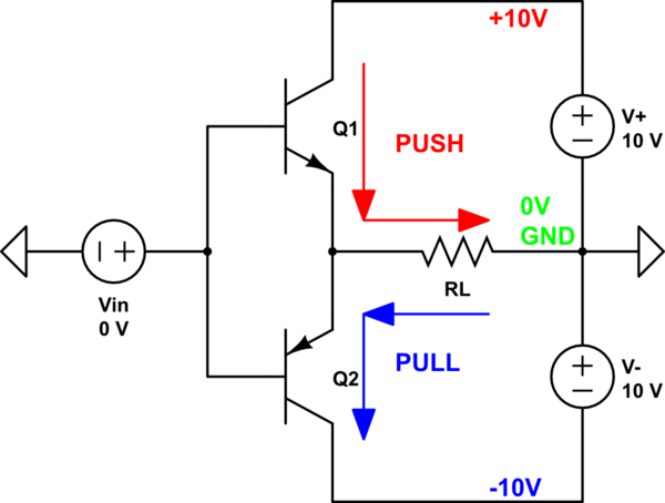
  • 0v or GND: In your schematic, the ground is halfway between the positive and negative supply voltages, or at 0V.
  • PUSH: When the upper transistor (Q1) conducts, it lets the current flow from the positive voltage through it and through the load (RL) to the 0V (zero volts) or ground point.
    Since the classic (conventional) direction of current is considered to be from positive to negative, this is considered pushing the current from the positive output to the ground, as well as "pushing" the voltage on the amplifier's output "up" towards the positive supply voltage.
  • PULL: When the lower transistor (Q2) conducts, the (conventional) current flow is from 0V/ground through the load (RL) and through the Q2 transistor to the negative supply voltage.
    Thus, it is called pulling, as it supposedly pulls the current from the 0V side of the load down to negative output of the amplifier, and also the voltage on the amplifier's output side down towards the negative supply voltage.
  • CONCLUSION: The upper transistor does the pushing, and the lower transistor does the pulling in this (type of a) circuit.

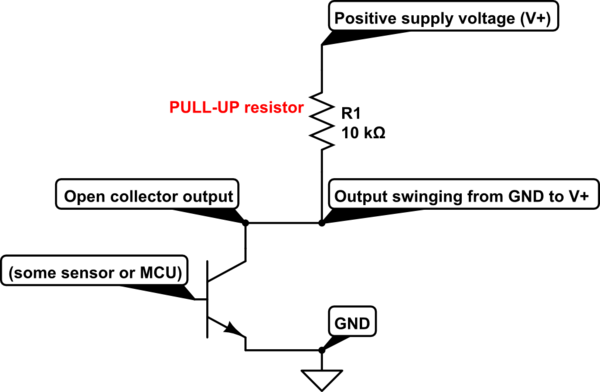
PULL-UP and PULL-DOWN typically refers to bringing an INPUT of a circuit UP to the positive supply voltage or DOWN to the negative side or 0V (zero volt) side to have a defined voltage level when there is no input signal and/or to change the voltage range of the input signal.
One example is an Arduino or ESP32 output only giving from 0V to +3.3V PWM signal, but you might need from 0V to +10V to drive a MOSFET. An ESP32 output drives an NPN transistor which is connected in an open-collector circuit where 0V remains about 0V, but the upper voltage or logic 1 now extends all the way to the positive supply voltage to which the pull-up resistor is connected.

AN EXAMPLE SCHEMATIC:

schematic

simulate this circuit

\$\endgroup\$
11
  • \$\begingroup\$ Great explanation... Just to ask, "And which way does the RL load "pull" - "up" or "down" :-)? I'm putting a smiley face because it might look quite strange to the reader... \$\endgroup\$ Commented Apr 23, 2023 at 21:43
  • 1
    \$\begingroup\$ @Circuitfantasist The potential on the left side of the RL (towards amplifier output) is "pulled-up" towards the positive voltage side when Q1 is on, and it is "pulled-down" towards the negative voltage side when Q2 is on. The ground or 0V side of the RL is the "reference point". Also, the RL or the load ITSELF is not doing the pushing or pulling, it is actually resisting the pushing and pulling of a current through it. \$\endgroup\$ Commented Apr 23, 2023 at 21:55
  • 1
    \$\begingroup\$ @Circuitfantasist You're right, I overdid it! :D Oops! The open-collector was supposed to be inside a sensor, but then I added MCU and confused myself.. \$\endgroup\$ Commented Apr 23, 2023 at 22:14
  • 1
    \$\begingroup\$ @Circuitfantasist Sorry, I have too many things to do, and I just sometimes catch a few moments to flex my brain and skills here. If my answer is acceptable to you, you should mark it as accepted answer. \$\endgroup\$ Commented Apr 23, 2023 at 22:37
  • 2
    \$\begingroup\$ @Circuitfantasist You're the one who asked and you're the one who decides which answer is more acceptable, helpful or better helps you understand, and that's the whole point. \$\endgroup\$ Commented Apr 24, 2023 at 8:58
4
\$\begingroup\$

From the point of view of the load \$R_L\$, Q1 pushes current into it, and Q2 pulls current from it.

I would not call an emitter-follower (which both transistors are, in this circuit) a pull-up or a pull-down, but terminology can vary.

\$\endgroup\$
1
  • \$\begingroup\$ So your explanation is based on the fluid analogy ("fish tank")? \$\endgroup\$ Commented Apr 23, 2023 at 21:14
3
\$\begingroup\$

Well, AFAIK, that's terminology that developed during the history of electronics with no coherent source. That is, it is not the result of the effort of a single author who wrote the basics of electronics terminology.

FWIW, I always assumed the meaning of "pull" in pull-up/down referred to the node voltage which was pulled toward a higher/lower voltage relative to ground.

OTOH, "push" and "pull" in "push/pull" refer not to voltage, but to current in the load, so a whole different context. What is relevant here is that the two kind of BJTs make the current flow in two opposite directions. Which is "push" and which is "pull" really doesn't matter, and I don't think the original "inventor" of this terminology meant something more than that.

In the end, I don't find it strange that the two meanings of "pull" are not in sync, since they refer to two different quantities.

\$\endgroup\$
1
\$\begingroup\$

Found [FAQ] What's the difference between logic output types (push-pull, open-drain, 3-state)? from Texas Instruments which says:

A push-pull output can source current in the high state or sink current in the low state.

Without further searching not sure if any standard terminology is in use by semiconductor manufacturers.

\$\endgroup\$

Your Answer

By clicking “Post Your Answer”, you agree to our terms of service and acknowledge you have read our privacy policy.

Not the answer you're looking for? Browse other questions tagged or ask your own question.