5
\$\begingroup\$

Today I was experimenting with voltage doublers and tripler for a hobby project demanding a voltage I can't directly pull from the transformer I have. The following measurements confuse me:

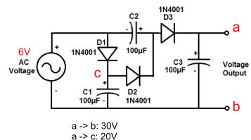
enter image description here

I was expecting three times the input voltage, so 6V x 3 = 18V output, but I got 30V measuring points a and b. When I measured points a and c I got 20V, "kinda" the voltage I was assuming to have at points a and b. I don't care much about two extra volts, since I need to regulate this and plan to use a 7815 if using the 20V, or 7824 if I use the 30V. My hobby circuit works from 12VDC to 25VDC.

I'm confused. Wasn't this supposed to multiply the input voltage by three? It seems to me it is quintupling it.

I was reading this.

\$\endgroup\$
4
  • 5
    \$\begingroup\$ 6V RMS or peak? \$\endgroup\$ Commented May 18, 2023 at 2:08
  • \$\begingroup\$ @TimWilliams it is an old UPS transformer, measuring the output with a multimeter shows 6 VAC \$\endgroup\$ Commented May 18, 2023 at 2:20
  • 2
    \$\begingroup\$ Loaded or unloaded? \$\endgroup\$
    – winny
    Commented May 18, 2023 at 7:32
  • 2
    \$\begingroup\$ About Tim Williams question: When speaking about voltages of non-DC signals (sine, rectangular ...), you have to say which voltage (RMS, peak ...) you are speaking about: If a DC signal has a voltage of 30V, it has a voltage of 30V. However a (non-sine) AC signal may have an RMS voltage of 3V and a peak voltage of 300V. (In the case of sine signals, the peak voltage is ~1.4-times the RMS voltage). This is very important when comparing AC to DC signals: Does the signal with 3V RMS and 300V peak have 10-times or 0.1-times the voltage of the 30V DC signal? \$\endgroup\$ Commented May 18, 2023 at 15:12

2 Answers 2

10
\$\begingroup\$

A simple simulation can show what you're seeing. I've re-drawn the circuit in the form typically used for a Cockroft-Walton multiplier.

The circuit you've used has a variation: C3 is referenced to ground. More usually, C3 would be connected to C1 - imagine the SW1 flipped the other way. Both variants do the same thing.
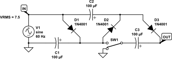
schematic

simulate this circuit – Schematic created using CircuitLab
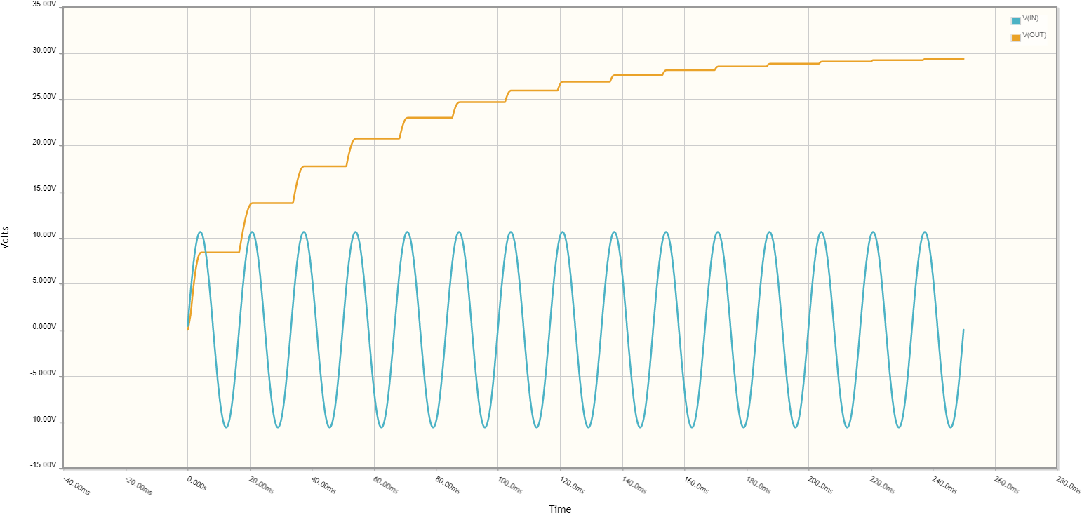
enter image description here

Note:

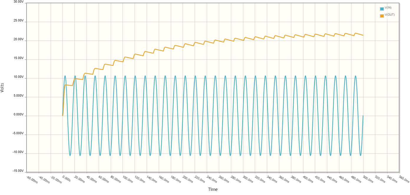
  1. Transformer output voltage is higher than nominal when the transformer is not loaded or lightly loaded. It's not unusual to see e.g. 7.5VAC RMS on a "6V" transformer. The simulation above runs the simulated AC source at 7.5VAC.

  2. The voltage being multiplied is the peak voltage, not RMS voltage. For a sine wave, \$V_{RMS} = V_{peak}\cdot\sqrt{2} = V_{peak}\cdot 1.41\$.

The circuit is also not able to support high load currents without going to much larger capacitors, and then the dissipation on the diodes will become a problem - and it won't matter how good the diodes are. When they are "good enough", the dissipation will occur in the transformer windings - whatever will be the next highest resistance area in the supply side of the multiplier.

Charging a capacitor from a voltage source always wastes half the energy used for charging as heat. As such, the multipliers are not efficient at all. They used for light loads, and are very popular in CRT anode supplies, since the currents needed there are small.

Let's see what happens with a 1kΩ load:
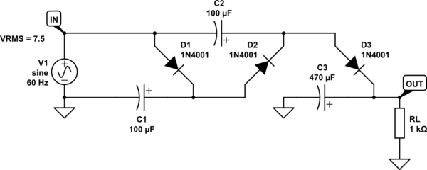
schematic

simulate this circuit

The output voltage is about 20V, with load current jusst above 20mA, and that's with C3 increased to 470μF:
enter image description here

\$\endgroup\$
3
  • \$\begingroup\$ Excellent answer. So this won't be able to work with a 6A load? \$\endgroup\$ Commented May 18, 2023 at 13:42
  • 4
    \$\begingroup\$ @AramAlvarez Nope. 60mA maybe and even that will have it run quite hot. You’re trying to save money by reusing the ups transformer right? So any solution that costs more than a proper supply makes no sense. Just buy a switching supply that does what you need. Ideally make it work from an ATX power supply since those can be had from surplus for almost nothing. \$\endgroup\$ Commented May 18, 2023 at 15:18
  • \$\begingroup\$ Worth mentioning: The reason Cn is normally connected to Cn-2 is because that allows you to use a lower-voltage capacitor for Cn; the maximum voltage across it (and every other capacitor in the circuit, except C1) would be just two times the input peak. This is more important in many-stage Cockroft-Walton generators where the output voltage can be several kilovolts; in that case, you can use much cheaper 300 V or so capacitors rated for mains filtering, rather than very expensive several-kV rated capacitors. In your case, all the voltages are low enough that it doesn't really matter. \$\endgroup\$
    – Hearth
    Commented Jun 21, 2023 at 15:44
7
\$\begingroup\$

When an AC source is described as 6 VAC, usually that refers to the RMS value, not the peak value. A 6 VAC(rms) source has a 6 x 1.4 = 8.4 V peak. When that is "tripled", one will get something closer to 24 VDC. The actual value will depend on loading effects.

\$\endgroup\$

Your Answer

By clicking “Post Your Answer”, you agree to our terms of service and acknowledge you have read our privacy policy.

Not the answer you're looking for? Browse other questions tagged or ask your own question.