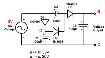
A simple simulation can show what you're seeing. I've re-drawn the circuit in the form typically used for a Cockroft-Walton multiplier.
The circuit you've used has a variation: C3 is referenced to ground. More usually, C3 would be connected to C1 - imagine the SW1 flipped the other way. Both variants do the same thing.
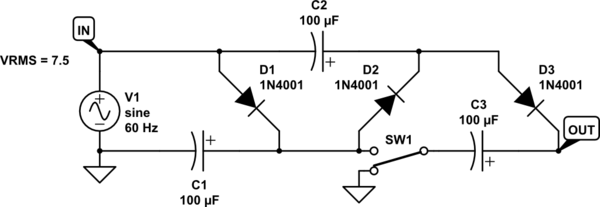
simulate this circuit – Schematic created using CircuitLab
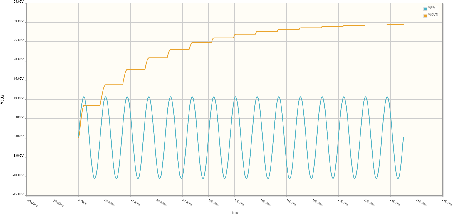
Note:
Transformer output voltage is higher than nominal when the transformer is not loaded or lightly loaded. It's not unusual to see e.g. 7.5VAC RMS on a "6V" transformer. The simulation above runs the simulated AC source at 7.5VAC.
The voltage being multiplied is the peak voltage, not RMS voltage. For a sine wave, \$V_{RMS} = V_{peak}\cdot\sqrt{2} = V_{peak}\cdot 1.41\$.
The circuit is also not able to support high load currents without going to much larger capacitors, and then the dissipation on the diodes will become a problem - and it won't matter how good the diodes are. When they are "good enough", the dissipation will occur in the transformer windings - whatever will be the next highest resistance area in the supply side of the multiplier.
Charging a capacitor from a voltage source always wastes half the energy used for charging as heat. As such, the multipliers are not efficient at all. They used for light loads, and are very popular in CRT anode supplies, since the currents needed there are small.
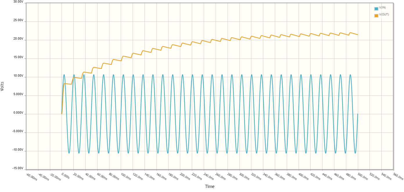
Let's see what happens with a 1kΩ load:
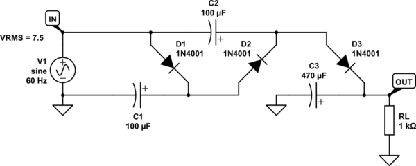
simulate this circuit
The output voltage is about 20V, with load current jusst above 20mA, and that's with C3 increased to 470μF:
