19
\$\begingroup\$

In operational amplifiers working in the negative feedback configuration, the voltage gain depends on the "ratio" of resistances. In most textbooks I have seen that both feedback and input resistance are in kiloohm.

If only ratio is important, then why don't we take resistor values in ohm or megaohm?

I have read on Quora (I am unable to find the link) that:

Kiloohm resistors are available in a wider range than ohm or megaohm resistors

This answer doesn't seem very convincing. Please clarify.

\$\endgroup\$
3
  • 2
    \$\begingroup\$ Sentences starting with "I have read somewhere that" are never worth blind trust. \$\endgroup\$ Commented Jun 7, 2023 at 9:09
  • 3
    \$\begingroup\$ If you've read something somewhere, then post a link or a reference to that material. [To paraphrase @Dmitry.] \$\endgroup\$ Commented Jun 7, 2023 at 23:36
  • \$\begingroup\$ @Dmitry I've edited the question. Thanks ! \$\endgroup\$ Commented Jun 8, 2023 at 9:13

8 Answers 8

17
\$\begingroup\$

Here is my answer in one sentence:

All the external resistors should be (a) large if compared with the opamps output resistance and at the same time (b) small if compared with the opamps input impedance (otherwise we are not allowed to neglect these opamp input/output impedances during calculations).

\$\endgroup\$
4
  • \$\begingroup\$ For 741 opamp, input impedance is about 2 megaohm and output impedance is about 80 ohm. So if we take external resistor values outside of these, according to your answer, it will complicate the calculation. Will it have any other impact ? \$\endgroup\$ Commented Jun 6, 2023 at 5:47
  • 1
    \$\begingroup\$ Yes - but there is no way-out. Lets take - as an example - a factor of 20 . In this case, resistor values between 1,6k and 100k are allowed. This factor of 20 will cause a maximum error not larger than a resistor tolerance of 5% . \$\endgroup\$
    – LvW
    Commented Jun 6, 2023 at 7:57
  • 1
    \$\begingroup\$ @MAJIDAHMAD Many op-amps behave rather poorly with DC loads below 1kOhm. Many op-amps have AC performance and DC gain specified at either 1kOhm or 10kOhm load resistance and not anything lower. Some high-speed/high-current parts may be fine with much smaller load resistances, but 741 is not one of those (not even close). \$\endgroup\$ Commented Jun 6, 2023 at 22:53
  • \$\begingroup\$ @LvW for the answer. Simple is better than complex ! \$\endgroup\$ Commented Jun 7, 2023 at 1:24
39
\$\begingroup\$

Your choice of resistor values will hinge on a few factors:

  1. Power. You want to keep things as cool as possible, and you want to avoid wasting energy, so that your power supply requirements are easy to meet, and your batteries last as long as possible. This usually means that you should aim for large resistances, to keep currents small, and to ensure that power dissipation in any resistors is low.

  2. Current. Many things are trying to impose potential difference across those resistors, and you need to work with currents that those devices are easily able to supply. This places a lower limit on resistances, and favours larger values over small. Where op-amps are concerned, their input requirements must also be considered. They may sink/source some small current too, and resistances must be chosen to keep signal currents appreciably larger than this, to avoid compromising op-amp behaviour. That places an upper limit on resistances you use in the op-amp's periphery.

  3. Interference. Unwanted currents will be induced in every path of your circuit, from various sources. They can arise from changing magnetic fields nearby, or from capacitive coupling to nearby mains wiring, or due to radio signals being picked up like an antenna, among others. These changing/oscillating currents may be small, but if they pass through a large resistance, that resistance will develop a significant potential difference according to Ohm,'s law \$V=I\times R\$. To mitigate this, we usually aim to keep resistances as small as possible.

  4. Noise. Every component in a system introduces thermal noise, including resistors. Sadly, this noise increases with the resistance, and if noise is a big concern, then again you would favour small resistances.

In other words, your choice of resistance values is always a balancing act, to satisfy the requirements of your circuit in terms of power, current ability of various elements, noise and immunity to interference.

As an example, take a typical inverting op-amp configuration (OA2, R1, R2), whose input is provided by a prior op-amp stage (OA1):
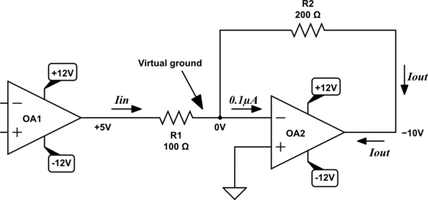
schematic

simulate this circuit – Schematic created using CircuitLab

Here OA1 is applying +5V at its output, and the inverting amplifier of gain \$-\frac{R_2}{R_1} = -2\$ should therefore produce an output of −10V. Let's calculate the corresponding input and output currents \$I_{IN}\$ and \$I_{OUT}\$, using Ohm's law:

$$ I_{IN} = \frac{(+5V)-(0V)}{100\Omega} = 50mA $$

$$ I_{OUT} = \frac{(0V)-(-10V)}{200\Omega} = 50mA $$

Considering that the largest current most op-amps are able to source or sink is about 10mA, clearly the outputs of both OA1 and OA2 are overloaded. The voltages we expect to be present in this design will not be achieved, because the op-amps are simply unable to comply.

If R1 and R2 are increased by, say, a factor of ten (1kΩ and 2kΩ respectively), then the currents involved are reduced by that same factor, to 5mA, which is within the capabilities of the op-amps, and will work just fine.

You could argue that increasing R1 and R2 by a factor of 10000 (to 1MΩ and 2MΩ) would also work, but then noise and interference become significant. Worse, \$I_{IN}\$ becomes so small that it is comparable with the op-amp's own input current (0.1μA in my example above):

$$ I_{IN} = \frac{(+5V)-(0V)}{1M\Omega} = 5\mu A $$

The closer \$I_{IN}\$ becomes to 0.1μA, the less "ideal" the behaviour of the system, and the less linear the relationship between input and output potentials.

Megohms is too much, hundreds-of-ohms is too little, and so here you would be considering values in the kilohms to hundreds of kilohms range. If this circuit is to be battery powered, then the higher end of this spectrum is better. If power supply isn't an issue, then the lower the better, kilohms is fine.

It just so happens that currents we tend to work with in signal-level systems like this are often in the tens of microamps to tens of milliamps range, and the voltages are usually just a few volts. Using Ohm's law alone, you can see that these conditions correspond to typical resistances in such typical applications, in the kilohms.

\$\endgroup\$
4
  • \$\begingroup\$ I suspect the direct reason everyone uses k-ohm resistors is that everyone else does and they copied them. I never tried to multiply all my resistances by 100x from normal, but I bet it would still work fine in some circuits. \$\endgroup\$ Commented Jun 7, 2023 at 9:22
  • \$\begingroup\$ @user253751 you're probably right! I hadn't even considered that! \$\endgroup\$ Commented Jun 7, 2023 at 10:15
  • \$\begingroup\$ @user253751 noise is a penalty. For low noise stuff this would not work. \$\endgroup\$
    – Designalog
    Commented Jun 9, 2023 at 9:33
  • \$\begingroup\$ @ErnestoG I said some circuits, not all. \$\endgroup\$ Commented Jun 9, 2023 at 12:17
9
\$\begingroup\$

Look at the datasheet for any op-amp and you will find the maximum current capability for the output. The total resistance the output sees is:$$R_{total}=R_{load}\parallel R_{feedback}$$ where \$\parallel\$ means in parallel with.

So the minimum total resistance is:$$R_{load_{MAX}}=\frac{V_{o_{peak}}}{I_{max}}$$

For example: if the op-amp can comfortably supply 2mA and the peak output voltage is 4V, then the minimum load resistance is 2kΩ

If the peak output voltage is 1V, then the minimum resistance is 500Ω.

If the peak output voltage is 10V then the minimum resistance is 5kΩ.

There are other factors like slew rate that may influence the choice of load.

On the input side, large resistances within an order of magnitude of the input resistance of the op-amp can cause measurable discrepancies in operation.

Again, there is no rule-of-thumb. As long as the boundaries and limitations of the op-amp and the requirements of the appication are met.


From Hearth's comment: With the modern push for battery powered operation, current consumption becomes a problem. Low value resistors consume more current. So the preference is to use values closer to the megohm range.

However, higher resistance generates more thermal noise, so a balance must be struck


There is no rule-of-thumb. As long as the boundaries and limitations of the op-amp and the requirements of the appication are met.

As always, read the data sheet.

\$\endgroup\$
1
  • 3
    \$\begingroup\$ This answer would be more complete with an explanation of why we don't go the other way for efficiency concerns and use TΩ resistors everywhere. \$\endgroup\$
    – Hearth
    Commented Jun 5, 2023 at 3:20
7
\$\begingroup\$

There are a bunch of considerations. For low frequencies, where power is not important and jellybean op-amps, resistances in the tens of kΩ to hundreds of kΩ are close to optimal. The optimal value range is not evident with ideal op-amps (eg. no bias currents, no input capacitance) or ideal circuits (eg. no parasitic capacitance). Typically the feedback resistor of 10kΩ or 20kΩ is good, which means the feedback current is less than 1.5mA (+/-15V supplies) to 150uA or so (3V supplies).

Op-amps have a bias current (or leakage current) that flows into or out of the inputs. Commercial op-amps have bias currents that might be in the range of close to 10uA down to a few fA. That's a range of >1000:1. A 20nA bias current (eg. LM358) into a 100kΩ resistance means an error of 2mV, which is in the same ballpark as the offset error of the op-amp, so getting significant.

Op-amps can only drive so much current from the output without excessive power dissipation or current limiting. Usually it's in 10mA to 30mA range for jellybean op-amps. So very low resistances can exceed that if the voltages involved are large. Plus it wastes power, which is very important in some applications.

Low value resistors have less Johnson-Nyquist noise, which is important in some applications.

Aside from bias currents affecting the DC output, using feedback resistors that are too high (without added compensation) reduces phase margin because op-amps have some input capacitance. High enough resistances with an op-amp that has a high input capacitance can result in oscillation. Some op-amps use a parallel interconnected array of perhaps 100 input MOSFETs (inverting and non-inverting input transistors interspersed) to help reduce offset voltage and drift, which results in relatively high input capacitance.

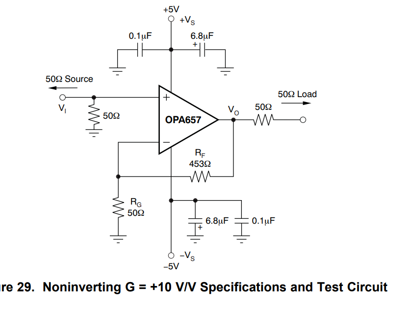
From here for example is a high-frequency amplifier circuit:

enter image description here

Relatively low resistance values are used because this circuit uses a 1.6GHz GBW op-amp and can have a pretty flat response with gain of 10 up to >100MHz.

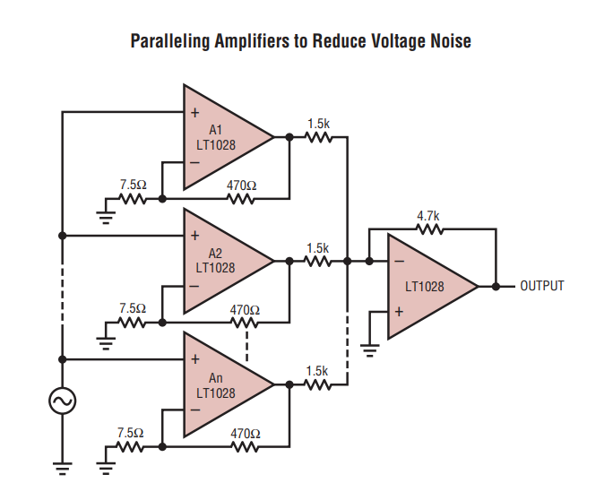
From here is another example of a circuit that uses quite low value resistors, this time for low-noise enter image description here

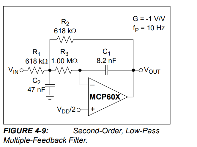
For low power, from here is an example of an active filter circuit that uses values in the MΩ range:

enter image description here

High value resistors mean that power consumption is less, and the capacitor values are proportionally lower in the filter circuit so there is more choice of capacitor types.

\$\endgroup\$
5
\$\begingroup\$

The simple answer would be: the fundamental trade-off between noise and power.

Larger resistors will draw less current. In a practical sense, this means the Op-Amps will not spend that much of their drive capability on the feedback network (when they are implemented with large resistors). Thus, small power dissipation due to feedback network.

However, the voltage noise associated with these resistors is rather large (i.e. \$\sqrt{4kTR}\$). You'd like to keep them small.

Therefore, we have a conflict.

The compromise is to use medium sized resistors. Most of the time, these happen to be in the \$10k\Omega-100k\Omega\$ range. But it's not always possible. Sometimes the noise specifications are so tough that all you can do is resort to capacitors to set your feedback network.

For any given linear network with n-nodes, if you duplicate this network and connect each duplicated node to its original node (i.e. a resistor that is connected between nodes a and b will now be placed in parallel with the same resistor value), you'll now get:

  • 2x current consumption
  • -3dB or \$\sqrt{2}\$ reduction factor in noise voltage
\$\endgroup\$
4
\$\begingroup\$

Due to op-amps does not have infinitive input impedance the high value resistors would cause a distortion on outputs of op-amps (bipolar input op-amps mainly). It is because some current from these resistors flows into inputs of op-amp and it corrupts the 1+R2/R1 ratio. With Mohm resistors it is more obvious.
Also considering input capacitance the Mohm resistors in feedback makes op-amp slower.
Induced noise is also the case.

On other hand the ohm resistors drain too much current form power supply.
Also outputs of op-amps are capable to sink and supply few mA only.

\$\endgroup\$
1
  • 1
    \$\begingroup\$ It's actually the JFET input opamps which typically come with warnings against distortion caused by using their inputs with high and/or differing impedance particularly in non-inverting configuration (particularly as unity gain voltage follower!) because of voltage-varying input capacitance. \$\endgroup\$
    – user107063
    Commented Jun 5, 2023 at 10:27
2
\$\begingroup\$

In addition to the answers you've gotten already, I think it's also worth mentioning that, in the case of current-feedback amplifiers--an unusual type of "op-amp-like" circuit that trades off precision for extremely high bandwidth--typical feedback resistances are in the ohms range--specifically a few hundred ohms to maybe 1 or 1.2 kΩ at the highest.

This is because the feedback signal in a CFA, as the name suggests, is the current into the inverting input, not the voltage at the input, so the resistances need to be low enough to allow the desired current through.

\$\endgroup\$
2
  • \$\begingroup\$ Perhaps add some sources for it? \$\endgroup\$ Commented Jun 5, 2023 at 22:39
  • \$\begingroup\$ @PeterMortensen This is from experience and dozens of datasheets I read recently trying to find a part that would work for a pretty particular purpose. This is the datasheet for the part I ended up going with; you can see recommended resistors for different gain values in table 9-2 on page 27. \$\endgroup\$
    – Hearth
    Commented Jun 6, 2023 at 0:34
0
\$\begingroup\$

Practical components are non-ideal:

  1. Op-amps have non-negligible input impedances, especially at AC. High input resistances can cause DC errors if the input DC currents are appreciable, and AC bandwidth limiting otherwise - input capacitances of op-amps, like those of most chips, grow with package size.

  2. Op-amps have limited drive strength, and heavy loading decreases their gain. This affects DC errors and stability.

  3. Small-valued resistors may eventually draw so much power that they'll turn into light-emitting resistors. Most materials found in PCB assemblies are ill suited to withstand incandescence.

  4. Power sources have limited power, so wasting a lot of it in feedback resistors is usually counterproductive.

\$\endgroup\$
1
  • \$\begingroup\$ Before resistors emit light, they get hot. Hot resistors are noisy resistors, defeating the point of picking low resistances in the first place. \$\endgroup\$
    – user107063
    Commented Jun 7, 2023 at 3:10

Your Answer

By clicking “Post Your Answer”, you agree to our terms of service and acknowledge you have read our privacy policy.

Not the answer you're looking for? Browse other questions tagged or ask your own question.