0
\$\begingroup\$

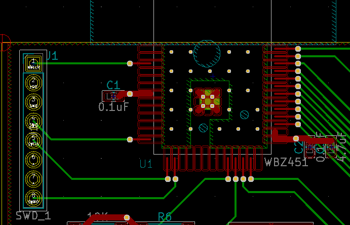
I have a WBX451, that's a BLE + blah module with a PIC32CX on it. I'm trying to program it with a PicKit4 using SWD. I have about 2 hour experience programming PIC controllers and 1.5 decade programming AVR controllers. This is where the module sits:

board layout

NMCLR, VDD, GND, SWO, SWCLK, NC, NC, SWDIO are the signals of the SWD_1 header. I stick it straight in the PicKit4 and go. It says "no good, you're trying at normal speed, why don't you try at low speed?". Well, because there's no such option. The speed (MHz) setting is simply ignored.

pickit4_options

This is the logic analyser thing from what happens.

enter image description here Hm. NMCRL should be active high. Here we see the exact opposite of it. I'm not sure why. The manual says that I may add a pullup. I may yes, like for the reset of an AVR. I have never in my life added a pullup and it has always worked. These things have an internal pullup. Then I have opened MPLAB IPE just to see if I find something useful there and I have found more confusion: confusion

Program speed setting is there, but does this mean that I have to have the IPE open too just for this setting?? The speed in Mhz is there too, also ignored. But where the program speed setting is! What PGC? What PGD? These are signals of the ICSP! The PIC32CX has no ICSP! Or does it? There no sich pins in the datasheet. And what's about the pullup (or pulldown) resistors? The datasheet says nothing about resistors! Can I please get some directions with this thing!

Oh, I have nice 3.3V between the GND and the VDD pins. The GND and VDD pins of the header are connected to fills that you can't really see on the image. MPLAB actually says "Target voltage detected". What am I missing here?

Update: I have fixed a contact problem on the NMCLR. New logic trace: enter image description here

So the NMCLR pulldown is there. From the duration of action I can tell that no matter what I do the programming speed stays the same.

\$\endgroup\$
4
  • \$\begingroup\$ Why did you choose an obscure BT module? Nevertheless, probably time to reach out to your local Microchip FAE or contact their ‘support’. \$\endgroup\$
    – Kartman
    Commented Jun 24, 2023 at 15:21
  • \$\begingroup\$ @Kartman, because of the multi-protocol thing, the external antenna connector, the 2M and long range PHY, the regulatory cert and because I have thought I try a PIC this time. I'm open for suggestions for alternatives. \$\endgroup\$ Commented Jun 24, 2023 at 21:58
  • \$\begingroup\$ There’s plenty of offerings with those specs. I’d suggest starting with a dev board as that gives you a working baseline. Going to a custom pcb first up is inviting troubles. Nevertheless, that is the situation you are in. If there is a reference design or dev board, use their schematic to compare with yours. What procedure do they use to flash and debug? There may be certain’magic’ you need to perform in order to activate the interface. Another trap is have you updated the firmware on the pickit4? \$\endgroup\$
    – Kartman
    Commented Jun 25, 2023 at 1:21
  • \$\begingroup\$ That's a chicken / egg situation. If I get a dev board it will surely work and I can program it, but when will I know if I can design a working PCB? €100 later?. Dev boards are ridiculously expensive. Microchip actually gives a lot of advice for the board layout. And for Zigbee 1 board is not enough. It's way cheaper to make 5 prototypes. Also, the dev board for this module includes the programmer, so it doesn't even give me the answer for the programming questions. Any idea for don-obscure modules? CC2652 from TI? \$\endgroup\$ Commented Jun 25, 2023 at 8:02

3 Answers 3

1
\$\begingroup\$

Ok, I got it to program. The clue: on the first logic screenshot SWDIO, SWCLK and NMCLR are all low. They should be all pulled up. Meaning that the board is not on at all. After fixing it the right wiring for the header is: NMCLR, VTG, GND, NC, SWCLK, NC, NC, SWDIO.

In the second logic screenshot is evident that the board is on. Removing the NMCLR wire or using a piece of wire between the board and the programmer solves the issue. I'm too lazy to hunt the problem but it's gonna be sone kinda impedance or interference issue. Definitely something with "i".

\$\endgroup\$
0
\$\begingroup\$

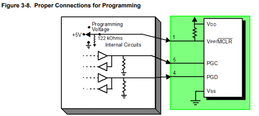
I'm working on the same module and in the WBZ451 manual, in the basic connections schematic, is shown how to connect the MCLR pin, from the layout I can't see if you have connected MCLR to VDD with a pull up resistor. That could be the problem. Let me know if it works, since I will also have to create the programming/debugging circuit.

Edit: in the same guide it is shown that it uses PGD and PGC input for programming through ICSP (PA8 and PA6 pad), maybe is more simple than the connection through SWO, SWCLK, NC, NC, SWDIO.

enter image description here

Edit2: Microchip told me that I cannot use ICSP interconnections. I must follow SWD programming interface as you did.

\$\endgroup\$
2
  • \$\begingroup\$ Paolo, this is very interesting. Your image shows a pullup to +5V, but the WZB451 is not 5V tolerant, VDD is +3.3V. I wonder what manual that is. The "PIC32CX-BZ2 and WZB45 Family Data Sheet" on page 56 says: "The module has sufficient filtering (0.1uF) and pull-up (10K) on the Reset line. On a typical application, no extra filtering is required on this pin." This tells me that these components are already on the board. \$\endgroup\$ Commented Aug 24, 2023 at 15:48
  • \$\begingroup\$ I clarified the situation by talking to microchip support. That manual I've linked is for many microchip product. To programme WBZ451 we have to follow SWD programming interface the same you have used. BUT WBZ451's datasheet (page 56) shows that MCLR is connected to VDD with a pull-up resistor. Also, on page 57 chapter 4.2.3-SWD Lines, it says: "provide an option for adding external pull-up on SWDIO". \$\endgroup\$ Commented Aug 25, 2023 at 16:49
0
\$\begingroup\$

there is a new rev, because the old one max. supports 3.0V max for programming. just power the device from the programmer (icd4 maybe). and for the mclr pin, no circuitry is needed. its all done on the module itself. ciao cacao :)

\$\endgroup\$
1
  • \$\begingroup\$ Thanks for the answer! I have already ditched the whole Microchip line. Their IDE is a pile of rubbish, their customer service is from a Kafka satire. The whole company is a waste of time. I use Laird products now instead. \$\endgroup\$ Commented Oct 18, 2023 at 6:40

Your Answer

By clicking “Post Your Answer”, you agree to our terms of service and acknowledge you have read our privacy policy.

Not the answer you're looking for? Browse other questions tagged or ask your own question.