0
\$\begingroup\$

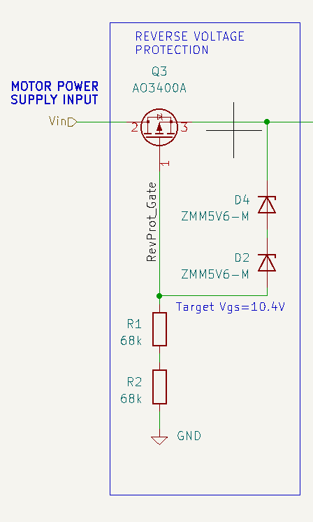
I am trying to do reverse-polarity protection on a 24V PCB. I read up on the PMOSFET method and I thought I had understood it, implemented it as follows:

schematic

If I connect the power supply correctly, the board works fine (so the circuit allows power through). But if I connect the power supply with the wrong polarity, it doesn't appear to protect it (luckily it's just passives after that component, but they become quite hot and obviously that shouldn't happen if they are being protected).

Any suggestions? I am confused.

\$\endgroup\$

3 Answers 3

5
\$\begingroup\$

AO3400A is an N-channel MOSFET.

\$\endgroup\$
1
1
\$\begingroup\$

You need a p-channel MOSFET; drain -> input; gate -> Zeners & resistor; source -> circuit.

When a + supply is applied, the FET's parasitic diode initially conducts from drain to source, and the circuit powers up (losing ~ 0.7 V). The resistors pull the gate voltage low, thus turning on the FET -- making it act as just a low value resistor. Everything is 'normal'.

With a - supply applied, the drain of the FET will pull negative (to the - supply voltage), at the gate and source will remain at about 0 V ==> The FET will be off and will protect the circuit.

Note that if your circuit likely has an input capacitor that could remain charged between application of a + supply followed by a - supply --> you'd need a FET with ~ 2x VIN breakdown capability.

\$\endgroup\$
-1
\$\begingroup\$

In your circuit, the MOSFET is connected backwards. The circuit works when power is applied correctly because the FET's internal body diode is conducting, bypassing the FETs channel.

In a high-side reverse-polarity circuit, the source is connected to the input and the drain is connected to the output.

As in your circuit, the gate overvoltage protection zener diode(s) connect between the gate and source.

But wait, there's more . . .

When a reverse-voltage is applied, the body diode can forward conduct. So the FET will behave correctly with a correct input, and conduct incorrectly with a reversed input.

The solution is two p-channel FETs in series, with the two sources tied together in the center. You get the high efficiency of "saturated" FETs, and the off-isolation of two back-to-back diodes when the input is reversed. Linear Technology has a line of power protection ICs that use this configuration. For example:

https://www.analog.com/media/en/technical-documentation/data-sheets/ltc4364-1-4364-2.pdf

\$\endgroup\$
2
  • \$\begingroup\$ Why the down-vote? \$\endgroup\$
    – AnalogKid
    Commented Jul 12, 2023 at 16:19
  • \$\begingroup\$ AnalogKid - Hi, Re: "Why the down-vote?" My guess (unless the downvoter replies) could be: (a) You didn't mention the OP has used an N-channel MOSFET. (b) Two P-channel MOSFETs aren't necessary for reverse polarity protection. The two MOSFETs driven by an LTC4364 serve different purposes - the one driven by HGATE is for surge suppression; it's just the one driven by DGATE which is for reverse-polarity protection. (c) Also see explanation of single P-channel MOSFET use by Infineon here. \$\endgroup\$
    – SamGibson
    Commented Jul 12, 2023 at 18:50

Your Answer

By clicking “Post Your Answer”, you agree to our terms of service and acknowledge you have read our privacy policy.

Not the answer you're looking for? Browse other questions tagged or ask your own question.