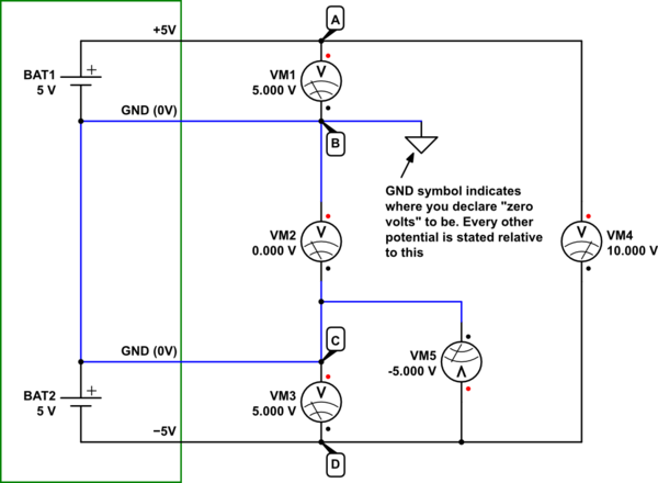
Here's an equivalent circuit which behaves exactly like your USB supply board. The green box represents the module:

simulate this circuit – Schematic created using CircuitLab
Potential (voltage) is rather like altitude; when you state an altitude, it's not clear how "high" that actually is, unless everybody agrees about where "zero altitude" is. That could be sea level, or the airport, or the centre of planet Earth, or any arbitrarily chosen reference point.
In the same way, we must declare some node (for example, A, B, C or D here) to be our "zero volt" reference point, and every other potential will be stated relative to that. That reference point is called "ground" (in keeping with the altitude analogy), and will be our "zero volt" point. Every other node will have some potential (voltage) relative to that.
In the above circuit, I have declared that node B shall be our "ground", and I tell other readers this with my use of the ground symbol.
Every voltmeter is measuring a potential difference, which is the difference between potentials at two points in the circuit. The reading on a voltmeter is not telling you the absolute potential at some point (with the exception I'll explain at the end). The voltmeter only tells you how different the potential at its red (+) terminal is from its black (−) terminal.
VM1 reads +5.0V. All this means is that node A is 5V higher in potential than node B. It is not saying that A is +5V, or that B is 0V or anything about the absolute potentials anywhere. I repeat, all this tells you is that node A is 5V higher in potential than node B, and without any more information, we can't know the absolute potential at either node.
VM3 also reads +5.0V. This means only is that node C is 5V higher in potential than node D. It is not telling you anything about the abosulte potentials at either node, only that nodes C and D are 5V different, and that node C has the higher potential.
As you know, the straight lines joining component terminals are wires, the purpose of which (besides carrying current) is to bring all interconnected terminals to the same potential. For instance, all points along any of the blues wires in my schematic have the same potential. In fact, they must therefore be the same node, and the labelling of nodes B and C is somewhat misleading here.
Nodes B and C are actually the same node, because they are physically connected together, and should really only have one name. Since they have the same potential, it should come as no surprise that voltmeter VM2 between them is measuring zero potential difference.
Since B and C have been designated "ground", this is my way of saying "here is 0V":
$$
\begin{aligned}
V_B &= 0V \\ \\
V_C &= V_B = 0V \\ \\
\end{aligned}
$$
Knowing this we are now able to state absolute potentials for A and D. VM1 tells us that A is 5V higher than B:
$$
\begin{aligned}
V_A &= V_B + 5V \\ \\
&= 0V + 5V \\ \\
& = +5V
\end{aligned}
$$
Similarly for node D, VM3 says C is higher than D by 5V:
$$
\begin{aligned}
V_C &= V_D + 5V \\ \\
V_D &= V_C - 5V \\ \\
&= 0V - 5V \\ \\
&= -5V
\end{aligned}
$$
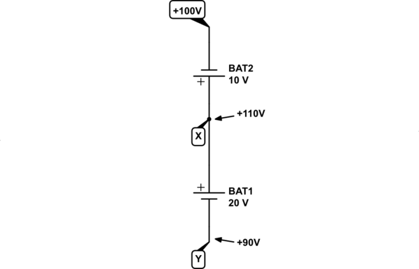
The module behaves as if it contains two 5V batteries. All a battery does (or any other voltage source for that matter) is impose a potential difference between its two terminals. It doesn't say what the absolute potential at either terminal is, only what the difference is. By connecting two such batteries in series, you are ensuring that the joined terminals have the same potential, but still none of the terminals in this arrangement have an quotable absolute potential until you designate some arbitrary potential to one of them:

simulate this circuit
Here I have declared that the top of BAT2 shall be called +100V. That battery ensures that node X shall be 10V more positive (check the polarity and orientation of BAT2):
$$ V_X = +100V + 10V = +110V $$
BAT1 causes node Y to be 20V lower in potential than X:
$$ V_Y = V_X - 20V = +90V $$
Understanding this will enable you to better see what's happening in the module. BAT1 and BAT2 in the module schematic are connected in series in such a way that BAT1 ensures node A is 5V higher in potential than our arbitrarily designated ground (0V) B/C, and BAT2 sets node D 5V lower than ground, at -5V.
Hopefully, now it should be clear why voltmeter VM4 shows +10V. That is the difference in potentials between nodes A and D:
$$
\begin{aligned}
V_A - V_D &= (+5V) - (-5V) \\ \\
&= +10V \\ \\
\end{aligned}
$$
A voltmeter never shows an absolute potential, unless its black negative terminal is connected to ground. This is not the case for voltmeter VM4, and therefore you should not expect it to show any kind of absolute potential. VM1 and VM5, however, do have their negative terminals connected to 0V. Notice how they both show the absolute potentials \$V_A\$ and \$V_D\$ respectively:
VM1 is showing \$V_A - V_B = V_A - 0V = V_A = +5V\$.
VM5 is showing \$V_D - V_C = V_D - 0V = V_D = -5V\$.
In case this hasn't sunk in yet, there's no such thing as 0V, only potential differences.
The physics of it, briefly is like this; "potential" is named after potential energy. Like a mass having gravitational potential energy, charges have electrical potential energy. A mass's potential energy is increased by moving it further away from Earth (physically lifting it higher), but the amount of potential energy it possesses is always stated relative to some fixed altitude. The ground, or if you're at the top of the cliff, the sea, or if it can fall into a hole towards the Earth's core, the centre of the Earth. We measure gravitational potential energy by how far it is permitted to fall.
If an electric charge is permitted to fall in an electric field, from node to node, it can't fall further than the node with lowest potential in the circuit, and that's what defines the maximum amount of energy it can impart to whatever it travels through on its way there. That's why voltage is always relative. If ever it reaches an "altitude" of 0V, but there exists still lower potential that it can fall to (say, -5V), then it will continue to fall (if permitted), in the same way that if a rock falls from 1000m to sea level (0m), it can still sink to the sea bed at, say -100m.
There the rock must stop, and all the potential energy it had at +1000m altitude has been spent heating the air and the sea, and making water waves and sound waves. Even though we defined sea level as a point where everything has zero potential, relative to that arbitrary level, the rock still has 100m further to travel (to the sea bed), and so the total energy it had to "spend" was actually related to the difference \$(+1000m)-(-100m) = 1100m\$.
That's like declaring the "ground" point in our circuit, but then also providing an even lower potential node, at -5V, towards which those charges could continue their journey, if permitted. Alternatively, we could have called node D ground. Then \$V_D=0V\$, and \$V_A=+10V\$. The two scenarios are equivalent. Whatever way you look at it, charges found at node A have 10 units of potential energy per charge more than charges found at node D, as indicated by VM4. That's the amount of energy that charges have to "spend" on their environment as they journey from A to D, and this will be the case irrespective of where we call "zero".
A charge starts its journey with a certain amount of potential energy, and "falls" towards a point in the circuit with lower potential, losing that potential energy on the way, donating it to whatever it encounters. If ever it reaches the point of lowest potential in the circuit (-5V in your module), its journey ends, unless it can somehow be "lifted" to the top again (+5V).
Potential (voltage) is a measure of how much potential energy is possessed by charges found at some location, some node, relative to the energy possessed by charges at another location. It's therefore also a measure of how much energy it has to impart during its journey between those locations, as it "falls" in the electric field, to cause heating, or turn a motor, or cause an LED to emit electromagnetic waves of light.
Oh, and by the way, due to the similarity between the scenarios of falling masses and falling charges, it really, really helps to draw schematics as you would draw a picture of a rock rolling down a cliff; with higher potential nodes at the top.
As humans we are all very familiar with principles of gravity, masses, and falling, and we all share a common idea of "up" and "down". It makes sense to help your readers understand the operation of a circuit by drawing schematics that conform visually with those same principles. It also makes circuits easier to troubleshoot.
It's not always possible, of course, but do it when you can.
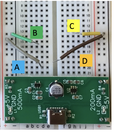
If you turn your photo clockwise by 90°, I bet you'll suddenly see how obvious and simple all this becomes. Try it.
Also, I recommend that you use your multimeter to measure the electrical resistance between B and C (while it's un-powered, of course). It should be 0Ω, proving that they are physically connected together inside the module, somehow.
Notice how every voltmeter measurement between B and C in your table is zero, telling you that there's no difference in potential between those two nodes:
$$ V_B - V_C = V_C - V_B = 0V $$
You may interpret this to mean that whatever absolute potential \$V_B\$ exists at node B, it must be equal to the absolute potential \$V_C\$ present at node C.
Therefore, in response to your titular question "why is there a voltage difference between these two grounds?": Grounds B and C are not different. Your own measurements have shown this.


grayto be+5 Vandgreento begnd, so don't get fixated onredandblackto mean something specific \$\endgroup\$