2
\$\begingroup\$

I want to combine 2 identical PCB antennas to increase gain. The antennas are designed to work on 2.4GHz and have 50ohm impedance, linear polarization with Omni-Directional radiation pattern, they are supposed to be used in this way: a combined couple horizontally oriented in the bottom of a weather balloon, and another couple in ground station (this one could be used vertically oriented eventually). The goal is to improve communication between the weather balloon and the ground station. enter image description here I'm wondering what would be the proper approach to do this without mess with antennas frequency range reception and worse performances in desired frequency range rather than improve them.
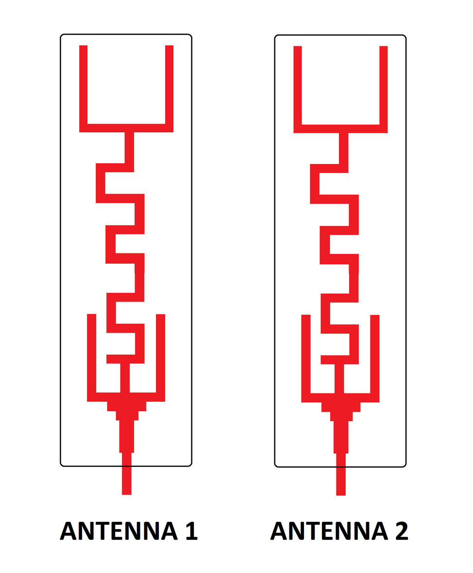
E.g. Consider the following scheme. enter image description here
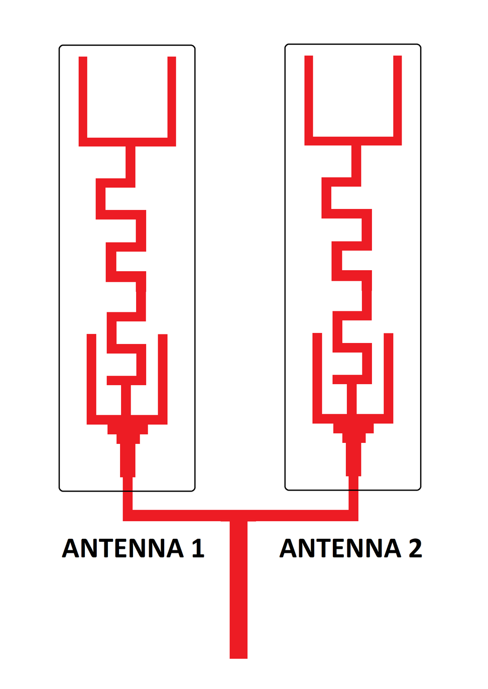
Is combining them in following way correct? If no, what should I expect from this configuration and what would be the proper way?

NOTE

I'm not talking about "antenna diversity" (that is based on the use of multiple different antennas that work separately and it requires additional hardware and integration), but to create a single bigger and more powerful PCB antenna combining 2 smaller antennas together.

\$\endgroup\$
15
  • \$\begingroup\$ The keywords you're looking for are either "phased array" or "diversity". Follow the recommendations of the radio(s) you're working with. \$\endgroup\$ Commented Sep 3, 2023 at 16:56
  • \$\begingroup\$ @TimWilliams Antenna diversity is another thing and it is based on different transmission strategy to use 2 antennas that work separately and so it requires additional hardware and integration. I'm looking for a way to create a bigger single PCB antenna combining 2 smaller antennas. \$\endgroup\$
    – AndreaF
    Commented Sep 3, 2023 at 17:00
  • 5
    \$\begingroup\$ "The antennas ... have ... linear polarization with Omni-Directional radiation pattern" -- yes, they do; but what do you want your combination to have? You can't have omnidirectional gain :) \$\endgroup\$ Commented Sep 3, 2023 at 17:29
  • 1
    \$\begingroup\$ If you want to improve communication with a distant receiver, it is easiest to buy directional antenna made for that purpose. What you're doing here is trying to build a directional antenna from multiple omnidirectional ones. That is possible but requires a fair amount of work and understanding of antennas and electromagnetics when you could simply buy an inexpensive product designed for that purpose. \$\endgroup\$ Commented Sep 3, 2023 at 18:03
  • 1
    \$\begingroup\$ How high will this weather balloon be operating? I suspect you will quickly run afoul of maximum ERP (effective radiated power) trying to communicate with common 2.45GHz devices over such distances (~km?). Far more than two antenna elements would be required to operate such a link. More likely a licensed telemetry or other link system will be the easiest solution. \$\endgroup\$ Commented Sep 3, 2023 at 20:29

2 Answers 2

6
\$\begingroup\$

There is no one correct, there's just correct for your situation.

We live in a universe where energy (and, hence, power) is conserved. So once you've made your antenna reasonably efficient, the only way to increase gain is to make it directional.

Making an antenna directional means that in transmit, energy is radiated in a restricted number of directions (usually one by design, with some parasitic sidelobes). In receive, the antenna has the same pattern, it's just that it doesn't respond to signals in the "off" direction, only in the directions where it is sensitive.

The more you make your antenna directional, the more important it is to have it pointed in the correct direction. If you had a purely omnidirectional antenna, then it would radiate and receive equally in all directions. If you make an antenna with 20dB of gain, then it must have an effective main lobe area of roughly \$0.04 \pi\$ steradians (out of \$4\pi\$); e.g. one that radiates to a circular patch would have a beamwidth of about 36 degrees if I'm getting my math right.

If you put a highly directional antenna somewhere that the orientation is changing in an uncontrolled manner -- such as a weather balloon -- then you only get a strong signal back when the antenna happens to be pointed your way -- the rest of the time it's worse than an omnidirectional antenna.

What you need to do, in your situation, is to first design the desired antenna pattern for each station. You need to keep in mind that you have a balloon that's going to take on fairly random directions. Then you need to look hard at the requirements for the ground station -- i.e., whether you can actively point the ground antenna, what you would do if a high-gain antenna loses the direction to the balloon, etc.

Once you have your candidate antenna patterns designed (and for any old balloon and any old ground station it may be that omnidirectional is, indeed, best) then you can worry about how to achieve that pattern.

\$\endgroup\$
2
  • \$\begingroup\$ Clearly more directionality had its drawbacks but the idea is to trade off part of its "omnidirectionality" to improve performances for my use case and I thought that having 2 properly combined antennas instead of one, doubling the surface could be useful to improve performance, \$\endgroup\$
    – AndreaF
    Commented Sep 3, 2023 at 19:22
  • 1
    \$\begingroup\$ Doubling the surface MAY improve sensitivity if the two antennas are placed far enough apart, at least a wavelength, maybe two, depending on the particulars of each antenna. But distances like that create other problems (multiple main beams in real space) that may or may not matter to you. \$\endgroup\$
    – SteveSh
    Commented Sep 3, 2023 at 20:22
4
\$\begingroup\$

If the individual elements are linearly polarized and "omnidirectional" then what they really have is a doughnut-shaped pattern. With the antennas vertical, then they are omnidirectional in the horizontal plane.

If you mount the antennas in a parallel configuration, as you drew, it will result in a directional pattern with peaks and nulls.

If you mount them in a straight line, one above the other -- called a collinear array -- then you will still have an omnidirectional pattern, but the "doughnut" will be flattened somewhat as it's been stepped on. If you look at TV and FM antenna transmitting towers, you'll see multiple elements stacked vertically in this manner. It provides more power along the horizon by wasting less power heading up into the sky and down toward the ground.

But you must also create a divider/matching network to feed both antenna elements in phase. You can't just connect them in parallel, because the result would be a 25 ohm feedpoint impedance. The network can be designed in microstrip but that's beyond the scope of the question.

\$\endgroup\$
3
  • \$\begingroup\$ Thanks for the answer. So if I connect them one above other the radiation pattern will be more "directionally constrained" but with more gain? If I have understood well this could be an option. Correct me if I have misunderstood. \$\endgroup\$
    – AndreaF
    Commented Sep 3, 2023 at 19:15
  • \$\begingroup\$ Is the weather balloon directly above the ground station? In that case you would be better off with circularly polarized antennas, and a completely different design. \$\endgroup\$ Commented Sep 4, 2023 at 4:47
  • \$\begingroup\$ @MarkLeavitt assuming zero wind seems rather optimistic. Typical weather balloon rise rates and burst altitudes mean a couple of hours aloft, and winds at altitude are stronger and steadier than at the surface \$\endgroup\$
    – Chris H
    Commented Sep 4, 2023 at 10:27

Your Answer

By clicking “Post Your Answer”, you agree to our terms of service and acknowledge you have read our privacy policy.

Not the answer you're looking for? Browse other questions tagged or ask your own question.