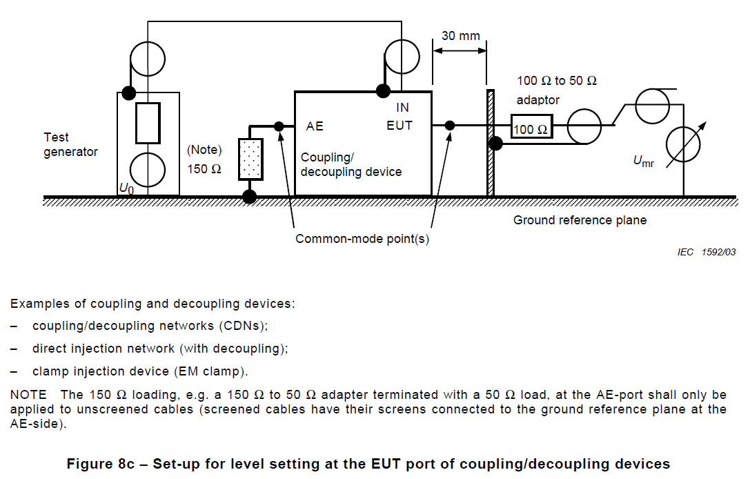
I am seeking some clarification around CDN calibration for 61000-4-6 (RF conducted immunity test).
By following the standard and some application notes, I am pretty sure I have it sorted. I just have one question.
If you look at figure 8c in 61000-4-6 it does not show the 6 dB attenuator in the setup for level setting at the EUT port of coupling/decoupling devices.

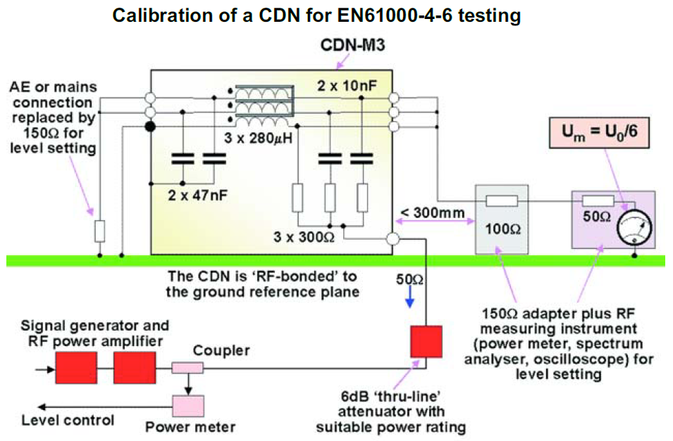
Whereas in the application notes I have read, it shows the 6 dB attenuator in circuit.
 http://www.teseq.com/products/downloads/datasheet/NSG_4070.pdf
 https://www.emcstandards.co.uk/files/61000-4-6_immunity_to_conducted_rfi_1.pdf
To quote the application note.
It is important to be aware that the test levels are specified as the voltage into an open circuit, not the voltage that is actually applied to the EUT, nor even that which is observed on the measuring instrument during calibration. Because both source and load impedances are known during calibration the actual indicated voltage for an applied emf level can be calculated. For the CDN calibration jig, the source impedance is 150Ω, the load impedance is also 150Ω and the measuring instrument impedance is 50Ω. The indicated voltage must be multiplied by 3 to allow for the 50 to 150Ω conversion and again by 2 to reach the open-circuit voltage, hence the indicated value is 1/6th the desired stress level.
Nowhere does it talk about the 6 dB attenuator’s effect on calibration.
My question: I kind of understand that the purpose of the 6 dB attenuator is to help match the impedance between the two circuits (correction, The 6dB pad is to improve the 50ohm output impedance of the 'generator assembly' at the test cell), but I don’t understand how it doesn’t influence the calibration level.
