I really love the answers you already have (+1 to both) and I really think that what they've written is more than enough to get the job done for you. But I may as well offer the thought process of yet another person. You've got two thrown at the wall to see if either sticks. So here's a third.
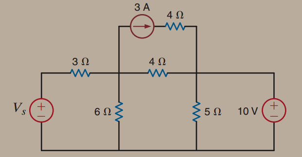
Usually, the very first thing I do is figure out which node to call ground. And this may mean (not often) that if there is already a ground called out I might change it to simplify my analysis. You get to call any one node ground. So use that power well! In this case, I'd do the same as most everyone else would but also just as the schematic almost already suggests:
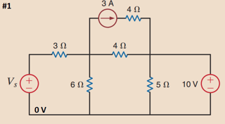
The next thing I do is label parts (if not labeled) and label nodes (if not labeled.) It's always better to get into the practice of working with symbols than specific values unless your only goal is a quick answer on a timed test. Otherwise, label everything under the sun and use the labels.
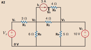
The next thing I do is to remove stuff that is getting in the way. And now you know that \$R_4\$ is a complete waste of time worrying over. It's an entirely separate circuit and for now (but not later) should be dead to you except to note that \$I_{R_4}=2\:\text{A}\$.
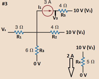
It's usually only now that I go back to see what information was provided on the problem. I've cleaned up a few things and managed to completely eliminate one part from my view. One less thing to be confused about, I say! But this is the point where I start to apply what's been added.
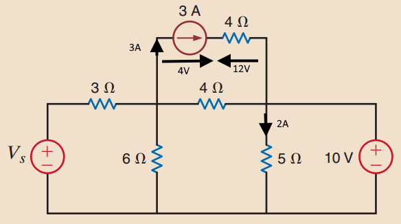
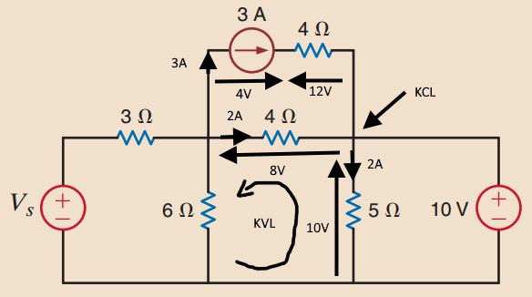
The current source is providing \$12\:\text{W}\$ of power. So \$V_3=V_2+\frac{12\:\text{W}}{I_1=3\:\text{A}}=V_2+4\:\text{V}\$!
\$\mid I_{R_5}\!\!\mid=I_1\$ so the voltage drop across \$R_5\$ must be \$\mid V_{R_5}\!\!\mid=I_1\cdot R_5=12\:\text{V}\$, with the (+) side being the one pointed at by the current arrow. it then follows that \$V_1=V_3-12\:\text{V}\$ and \$\therefore V_3=22\:\text{V}\$.
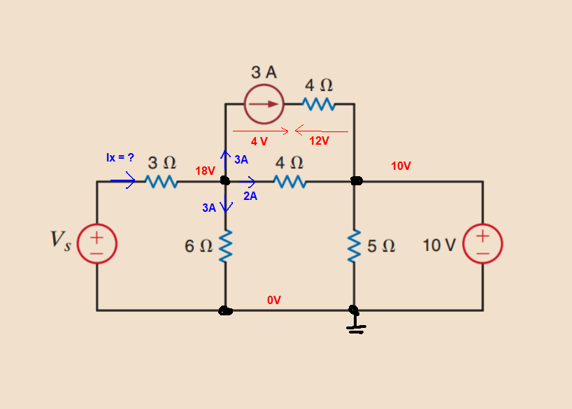
From #5 (\$V_3=V_2+4\:\text{V}\$) and #6 (\$V_3=22\:\text{V}\$), find \$V_2=V_3-4\:\text{V}=18\:\text{V}\$.
Redraw schematic with this new information and add the following now-known currents: \$I_{R_2}=\frac{V_2-V_1}{R_2}=2\:\text{A}\$ and \$I_{R_3}=\frac{V_2-0\:\text{V}}{R_3}=3\:\text{A}\$. The sum of the currents leaving node \$V_2\$ is \$I_1+I_{R_2}+I_{R_3}=8\:\text{A}\$. So add that current, as well, onto the schematic:
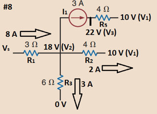
The (+) side of \$R_1\$ is where the tip of the current arrow points into (not out of), so this means the (+) side is on the left of \$R_1\$. Therefore, \$V_s=V_2+R_1\cdot 8\:\text{A}=42\:\text{V}\$.
The last question is about the power in/out of \$V_1\$. Here, you want the current into/out-of \$V_1\$. There is \$I_1\$ entering the \$V_1\$ node, plus \$I_{R_2}\$ also entering the \$V_1\$ node. But \$I_{R_4}\$ exiting the \$V_1\$ node (#3 above.)
So the resulting magnitude is \$3\:\text{A}+2\:\text{A}-2\:\text{A}=3\:\text{A}\$.
But this magnitude is going into \$V_1\$ and not leaving out of it. So it is absorbed power. \$V_1\$ is being charged, so to speak.
This means we use a minus sign to represent its power. So the result is that the power for \$V_1\$ is \$10\:\text{V}\cdot -3\:\text{A}=-30\:\text{W}\$.
Those are the micro-steps I'd mentally take if forced to explain things, in detail. However, what really happened for me was that I could quickly see that there were just \$8\:\text{V}\$ between \$V_1\$ and \$V_2\$ and since I knew that \$V_1=10\:\text{V}\$ I then immediately knew that \$V_2=18\:\text{V}\$. From there it was just a matter of seeing the currents, adding them up, and applying the net result at \$V_2\$ as a current in \$R_1\$ to see that \$V_s=42\:\text{V}\$. And then a similar mental sum to get the power into/out-of \$V_1\$.
It wasn't my intent to provide specific values. I was just trying to do what you asked, show you a process I'd follow. You already had the results, anyway. So including them above is just illustrative only. The main thrust of the above is the approach. Not the quantities, so much. They are just there to help clarify anything I failed to write more about, is all.





3 A * 4 V = 12 W. It's basic. Do you not see this? \$\endgroup\$