10
\$\begingroup\$

Given I have designed and produced an RF circuit with an output for connecting an antenna. I know this antenna has an input impedance of 50Ω. I now wish to measure the actual output impedance of my circuit, before connecting the antenna, to ensure that the impedance matches.

How do I actually measure the output impedance of my circuit?

And additionally, can I do this with hobby friendly priced equipment?

Update: I know the basic theory of impedance matching, but I have never understood how to actually do it. So I am really asking for input on the specific hardware and equipment to use, and how to perform actual tests.

The RF circuit is operating in the UHF range, and transmits about 10dBm, if this helps.

\$\endgroup\$
8
  • 1
    \$\begingroup\$ Does "Hobby Friendly" include an oscilloscope? Also, do you wish to know the physical output impedance, or calculate the theoretical output impedance? \$\endgroup\$ Commented Nov 18, 2010 at 19:09
  • \$\begingroup\$ Well, yes, I consider oscilloscopes in the hobby friendly zone. However I don't think a spectrum analyzer is in the hobby friendly zone, and I know any oscilloscope which has a high enough bandwidth to measure UHF and above (directly). \$\endgroup\$
    – bjarkef
    Commented Nov 18, 2010 at 19:20
  • \$\begingroup\$ I asked a similar question about trace impedance: electronics.stackexchange.com/questions/5778/…. I think the answer is to design in the 50 ohms impedance, not to calibrate it after manufacture. \$\endgroup\$
    – Thomas O
    Commented Nov 18, 2010 at 19:21
  • \$\begingroup\$ Hi Thomas. I looked at your question, but I still do not understand how to actually measure what output impedance I have achieved, or how to design that in for that matter. Your question concerns the characteristic impedance for a transmission line. I am interested in the output impedance of a RF generator circuit (+ possibly the transmission line), and I don't understand how this relates. Please enlighten me? :) \$\endgroup\$
    – bjarkef
    Commented Nov 18, 2010 at 19:34
  • \$\begingroup\$ @bjarkef, Thomas is incorrect here, although they are both RF related, your applications are fundamentally different. I have done both, designing a trace to be 50 ohms is very easy, getting an RF generator to match can be quite challenging. \$\endgroup\$
    – Kortuk
    Commented Nov 18, 2010 at 21:51

4 Answers 4

6
\$\begingroup\$

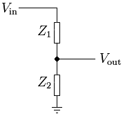
In general, to measure an output impedance, you just connect a known impedance across it and measure the drop in voltage level. You can then calculate the source impedance using the voltage divider rule.

voltage divider

Vout = Z2/(Z1+Z2)*Vin

You know these:

  • Z2 (known load)
  • Vout (voltage with load)
  • Vin (unloaded voltage)

So you can calculate the output impedance:

Z1 = ((Vin - Vout)*Z2)/Vout

In other words, Vin and Z1 are inside your device that you're measuring, and Z2 is the test load you connect across its output.

alt text

If the impedance varies with frequency, you can do the same measurement multiple times with sine waves of different frequencies. If you need to know the reactance, you'll have to measure the phase change with and without the load connected.

At low frequencies, this can all be done with a single channel scope and hobbyist equipment. At UHF I'm not sure how much effect the test equipment, scope's impedance, probe capacitance and line length, etc. will have on the measurements.

\$\endgroup\$
5
  • \$\begingroup\$ Thanks for the answer. However this is where I get lost when I try to put theory into practice: I don't really have a Vin, this is not some passive circuit with an input and an output. It is a circuit with a microcontroller, and a radio IC, and some RF low-pass filters, and some sensors, and maybe other things. Sure the input is a battery with around 2.7v, but that may vary with time, and I don't really think that is meant by Vin. \$\endgroup\$
    – bjarkef
    Commented Nov 18, 2010 at 20:23
  • 1
    \$\begingroup\$ Vin is the voltage at the output with no load attached. If you measure with a high enough input impedance, the effect of the source's impedance should be negligible. Vout is the voltage with a load attached. In other words, Vin and Z1 are inside your source that you're measuring, and Z2 is the test load you connect across its output. \$\endgroup\$
    – endolith
    Commented Nov 18, 2010 at 20:27
  • 1
    \$\begingroup\$ This is great information, but as I note, this is applicable at RF frequencies, I note that you say this, I am just adding and extra note. \$\endgroup\$
    – Kortuk
    Commented Nov 18, 2010 at 21:17
  • 1
    \$\begingroup\$ Good information for low frequencies but you would have a really hard time taking this approach to design a matching circuit for RF frequencies. At least without some really expensive equipment. \$\endgroup\$
    – Mark
    Commented Nov 18, 2010 at 23:55
  • \$\begingroup\$ You wrote, "If you need to know the reactance, you'll have to measure the phase change with and without the load connected." Where can I find the equation to calculate reactance from phase shift? Will amplitude change be a part of that equation also? \$\endgroup\$ Commented Jun 17, 2022 at 2:12
6
\$\begingroup\$

You really need one of a number of options, none of them are hobby friendly if you are above a few MHz. I would guess you are at 2.4GHz, or at 900MHz.

Professional Options

If you might know someone whom has access to equipment that would help you have a few options.

  1. VNA- Vector Network Analyzer. This can give you a smith chart over a frequency range and make sure it shows you at 50 ohms. You can also measure S11 which should be less than -20dB
  2. Spectrum Analyzer- This should allow you to determine your power received at your frequency. This is not ideal, but it should get more output power as you get closer to a proper match.
  3. SWR Meter-As Is noted in another answer and I always forget about, you can use an Standing Wave Ratio meter, but I would still suggest a VNA. They have significantly more features, and can do anything a spectrum analyzer or SWR meter can do.

Hacker style ways to approach it

There is another funny way to approach this, the problem being you will need to build one of a few microwave components.

You could use an isolator and measure its temperature, hotter isolator is equivalent to a worse mismatch. this is not even close to good method as at 10dBm it will be very hard to detect a temperature failure.

You could build your own mixer and feedback your output signal and mix it with your signal returning from the connection. To take away your signal from the feedback you need to use what is called a circulator. This is not fun, but it is doable.

If you would like to try either method, which is similar to creating your own VNA, I can get you more information on how to build these devices.

\$\endgroup\$
7
  • 1
    \$\begingroup\$ I'm interested in the mixer method... got any more links? Thanks. \$\endgroup\$
    – cksa361
    Commented Dec 4, 2010 at 7:56
  • \$\begingroup\$ @cksa361, There are a number of options here. I would suggest you look into a "gilbert cell" to design this yourself, but there are many different approaches. Here google.com/… they have someone trying to analyze one. You will probably need a signal generator, like a Phased-locked-loop to generate your signal. This will not be any easy task. \$\endgroup\$
    – Kortuk
    Commented Dec 4, 2010 at 20:53
  • \$\begingroup\$ What is your budget like? I think I can find you some hobbyist projects that actually make most of what you need, then you only need to do a tiny bit of design. \$\endgroup\$
    – Kortuk
    Commented Dec 4, 2010 at 20:55
  • \$\begingroup\$ In 2022, Gilbert cell and an FPGA-driven SDR is an easy task. \$\endgroup\$ Commented Jun 15, 2022 at 16:28
  • \$\begingroup\$ Not every VNA can measure output impedance of an active circuit, because it is nonreciprocal, and the VNA measures only relatively to its own stimulus. In many cases, even the stimulus of the VNA (chepaer models like Agilent ENA) itself is unknown and pretty random. So the VNA should have a precision oscilloscope mode. Usually those are not VNA, but IQ impedance meters, which are limited by frequency range up to hundreds of MHz only. The technique you are referring to is called load-pull, ant there are special attachments to VNAs, quite expensive. \$\endgroup\$
    – Asdf
    Commented Jun 19 at 2:37
0
\$\begingroup\$

Another approach would be to use what is known as a "dummy" load. It basically a large resistor with the same impedance as your antenna. This will simulate your antenna.

For "tuning" most people use a SWR meter. If the impedance does not match a standing wave is reflected back to the transmitter from the antenna. With a prefect match the SWR ratio should be 1 to 1. There are several ways to adjust the impedance including shortening the antenna.

\$\endgroup\$
0
\$\begingroup\$

You can measure the source resistance of a transmitter by recording the RF output voltage with a 50 ohm load and paralleling a high value resistor (should be above 1000 ohms) and recording the new RF voltage and recording the calculated new value of the load resistance due to the added resistor.

Call the voltage ratio (first rf meas./second rf meas.) = N
Call the parallel load resistor = Rn
Call the source resistance = Rs

Rs = 50 x Rn x (N-1)/(50 - (N x Rn))

Using a high value resistor minimizes the Rs measurement error due to the transmitter source resistance being a dependent generator (value depending on the load resistance).

\$\endgroup\$

Not the answer you're looking for? Browse other questions tagged or ask your own question.