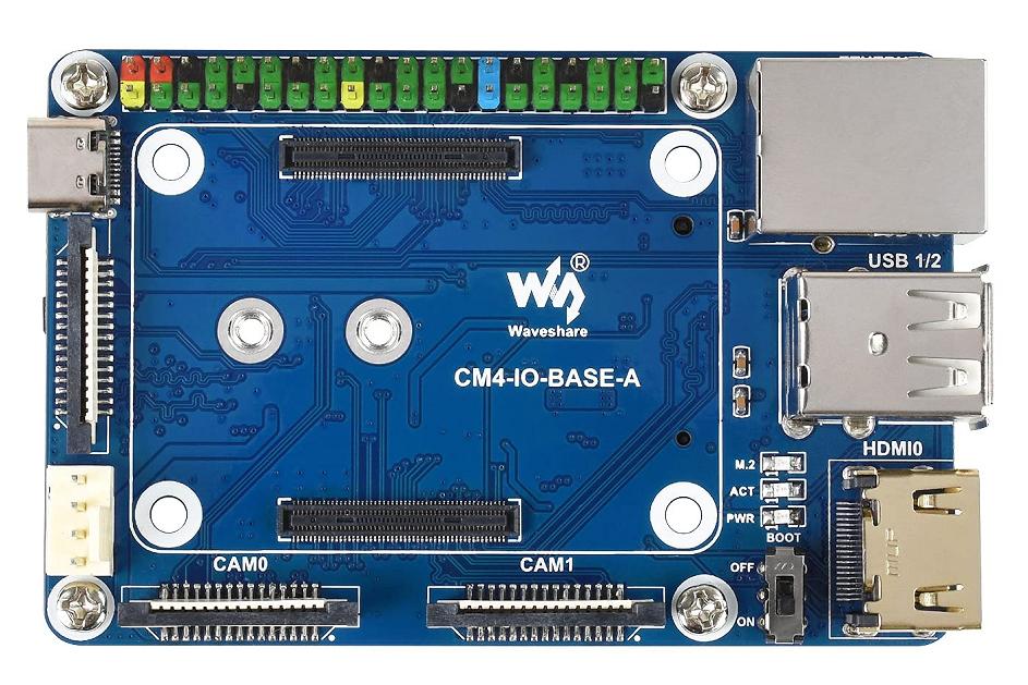
Evidently, it is possible, or, some are doing it. I notice the Waveshare Mini Baseboard,

(image obtained from: https://www.amazon.com/Raspberry-Standard-Color-Coded-Evaluating-Integrated/dp/B095CSRWXS?th=1 Mfg page: https://www.waveshare.com/wiki/CM4-IO-BASE-A (no affiliation))
But that doesn't mean it's a good idea.
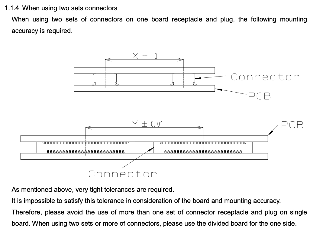
These are rigid connectors, meaning any positional mismatch of connectors on the two boards is likely to cause faulty connections -- compressing or stretching the contacts themselves, and by how much, depends even on the exact temperature and expansion rate of both.
The most precise alignment I can think of, would be a self-aligning process. Let's talk it through, to see how it would(n't) work.
You could try stacking the boards together, with one set of connectors pasted but not soldered. Send both boards -- the assembled and positioned stack -- through reflow. Either one board serves as positional reference, or both melt, and in either case the solder joints are aligned perfectly with no stress on the connectors. Mind, even getting them together in this way, is already a challenge; even with precise placement and an alignment jig, paste smear and risk of shorts is a risk here. Let alone bumping anything else, if you have nearby components and doing everything in one reflow operation.
We already have one immediate problem: the connectors are, at the very least quite soft, at soldering temperature. The plastic may indeed melt. Normally this isn't a problem, as the plastic has a gel-like consistency that retains its shape. But now we have two connectors wedged together, retaining the force of all those spring contacts. They may bulge apart, or lose planarity (on the soldering face), resulting in loose contacts, weak or broken solder joints, etc.
The problems only continue from there. The connector positions are frozen in place when the solder solidifies. If the boards have identical composition, they can have equal thermal expansion rate, and retain dimensional accuracy down to room temperature. But in general, boards will be made on different processes, from different materials, and almost certainly won't have equivalent copper density and component choice -- note that having a bunch of BGAs on one side increases stiffness of the board in the area, changes the overall expansion rate, etc. On dimensional scales of 10s µm, everything matters. The board surface itself warps in various ways, due to local differences in expansion (like components and copper areas). Displacements of this scale, multiplied by the elastic modulus of the board, result in forces of -- I would guess, in the ballpark of single to tens of newtons, at the connectors. Which is a lot for a little connector like that.
And even if your boards were fabbed on the same process, same materials, the fact that stiffness varies with copper density, board thickness, exact material condition (the material itself may vary enough from batch to batch to matter), means you'll have a hard time getting them to track on the cooldown from soldering to room temperature.
So what can we do about it?
Stiffness is the key. The looser the boards are positioned apart from the connectors, the less side force bears on them. A relatively thin-limbed 'U' shape board could be used, with a large gap between connectors, allowing flex between them, and thus more positioning error. Still maybe not a lot, but it's a start. We can compound this further by using much softer board material -- this type of connector is very popular with flex boards, which can be bent around corners as well; they're especially useful in compact electronics like cameras and cellphones.
But this isn't very convenient for rigid board-to-board applications, and the recommended approach (use just one connector) is best for that case.


