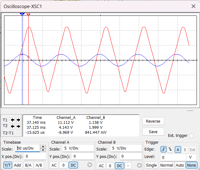
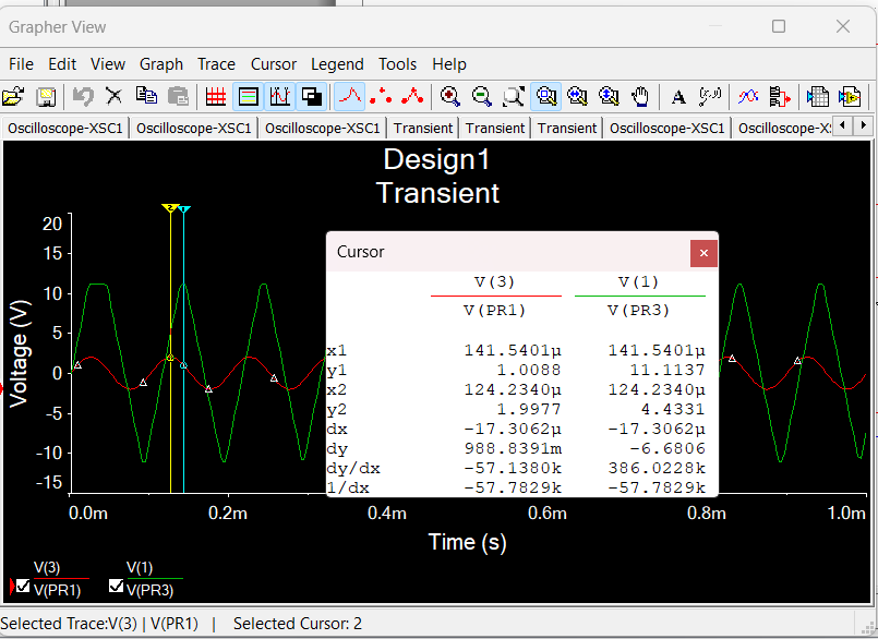
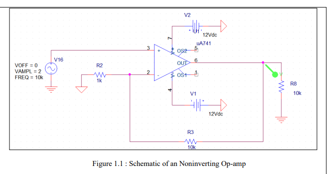
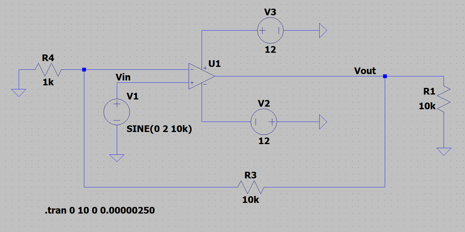
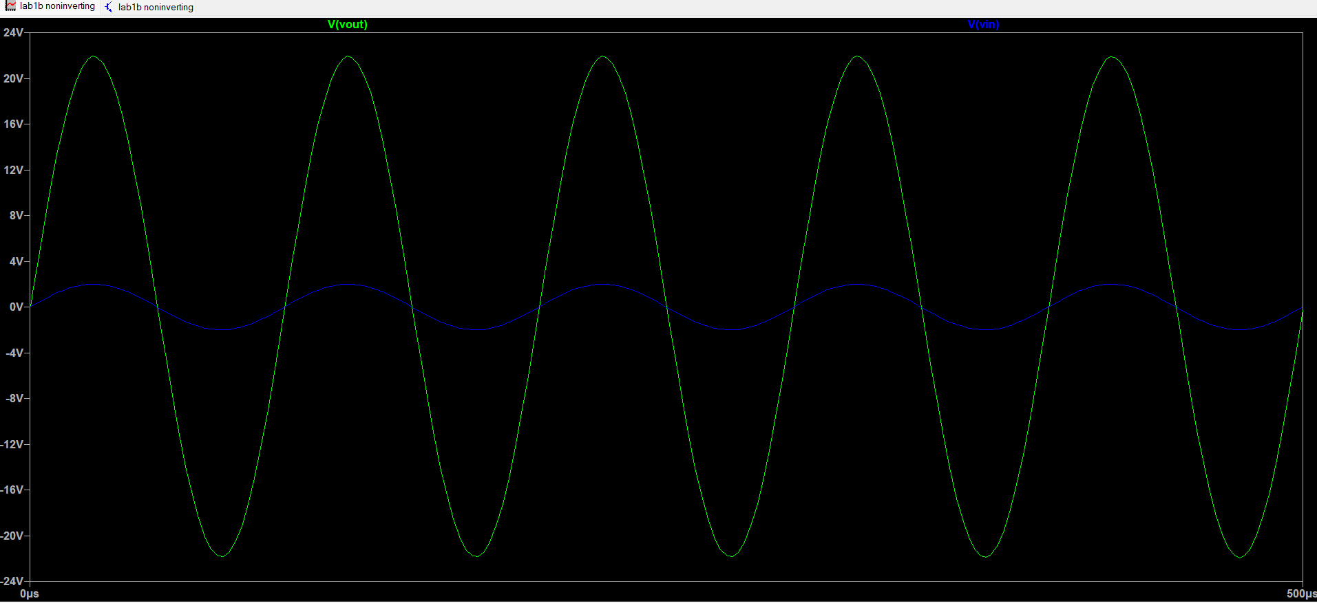
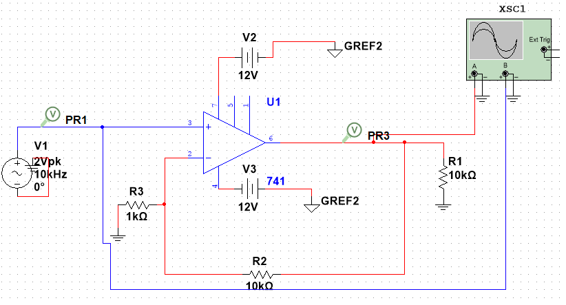
I am doing a simulation in multisim to simulate an non inverting amplifier, but i have gotten values that is not what intended. From what i know, the gain for non inverting amplifier is Va = 1 + Rf/Rin. In this case, Va = 1 + 10k/1k = 11, then the Va = Vout/Vin = 11. I can get Vout = 22. In this simulation, i get around Vout = 11.2, when Vin = 2, and i dont know why the vin and vout is out of phase. Before simulating in multisim, i did the simulation in LTSPICE, and the outcomes are better to my knowledge, as i get the Vout around 22, and the Vout and Vin are in phase.
-
\$\begingroup\$ The amplifier goes into saturation if Vo exceeds Vsat, i.e. the output has the peaks cut at +.12V. If Vout=12V then Vinmax=Vout/Gain=12/11. \$\endgroup\$– Francesco M.Commented Mar 8 at 13:26
1 Answer
In this simulation, i get around Vout = 11.2, when Vin = 2, and i dont know why the vin and vout is out of phase.
Your op-amp is fed from a +12 volt and -12 volt supply. This means that the biggest output peak that it can produce is 12 volts and, this is further limited by the output transistors inside the op-amp.
In addition, your op-amp is slew-rate limiting and this will cause an unwanted phase shift. This is what you see in your oscilloscope image.
The likely reason LTspice delivers an output waveform you anticipated is down to the simplistic op-amp "model" that you used. I'm referring to the mathematical "model" used by the simulator. A lot of models are too simple and you get strange things happening (as per what you saw).

