2
\$\begingroup\$

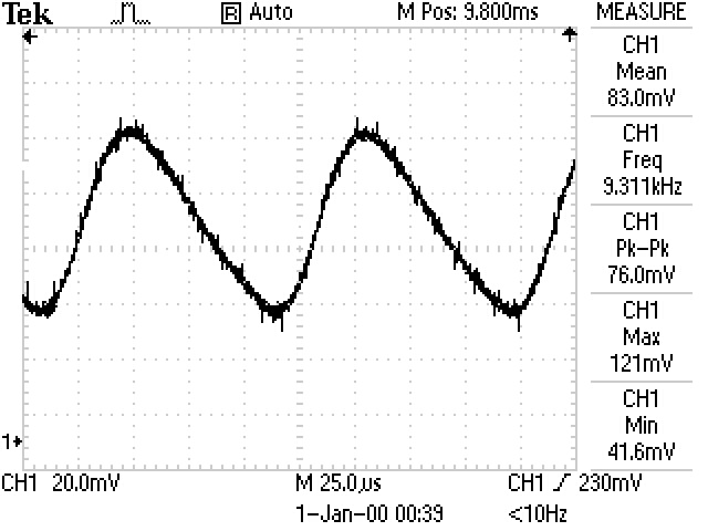
In this design, the 2A motor "M", which is running at PWM=10kHz, creates a lot of noise in the ground as shown on the scope trace. Not only the ground is sinusoidal but more painful, the ground level raises up to 80mV when the motor is running.

Unfortunately, this noise and the fact that "ground is at 80mV" make it very difficult to detect the very little voltage variation of the sensor "S".

Only one big 3.7V battery powers the motor and the processor. A very small 3.0V battery is powering independently the op-amp.

All the ground traces are extremely thick and have been designed as much as possible like a star. There are a couple of 100uF on the big 3.7V battery as well as mutliple 0.1uF. There is one 4.7uF and multiple 0.1uF on the small 3.0V battery.

What could I do to minimize this noisy ground?
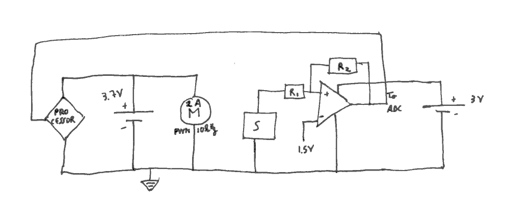
schematic

scope trace

\$\endgroup\$
7
  • 2
    \$\begingroup\$ Posting your physical layout would greatly help us help you. \$\endgroup\$ Commented May 30, 2013 at 20:29
  • \$\begingroup\$ This problem is somewhat similar to this one, and a similar approach might be called for. \$\endgroup\$
    – Dave Tweed
    Commented May 30, 2013 at 20:54
  • \$\begingroup\$ Is it really ground noise? What point of the circuit is scoped, and where is the ground clip attached? How is the 1.5V reference generated for the op-amp? By the way, the op-amp inputs appear to be backwards in the diagram: it looks like it should be an inverting stage with a V/2 reference at +. \$\endgroup\$
    – Kaz
    Commented May 30, 2013 at 20:59
  • \$\begingroup\$ What do you mean by "ground is at 80mV"? Ground is, by definition, 0V. Maybe if you pick one place and call that "ground", and compare it to another place and also call that "ground", then you can measure an 80mV difference. So don't do that. And don't let your sensitive components do it, either. \$\endgroup\$
    – Phil Frost
    Commented May 31, 2013 at 0:42
  • \$\begingroup\$ See this similar problem: electronics.stackexchange.com/questions/53914/… \$\endgroup\$
    – Phil Frost
    Commented May 31, 2013 at 0:44

2 Answers 2

2
\$\begingroup\$

Do you have a de-coupling capacitor on the motor itself? If not, add a 100 nF ceramic capacitor across the motor terminals, as closely as possible to the actual motor housing. (Worst case, across the connectors to the motor terminals on your board.)

Does the motor run only one way? If so, also add a dissipation diode across the motor, with anode towards ground.

To get a better measurement of the voltage across the sensor, you may be able to use Kelvin-style wiring (or "remote voltage sense" wiring) where the actual sensor wires are separate from the current carrying wires. Whether this works depends on how the ground for your 1.5V reference is created.

A separate battery for the motor only seems like a good idea. If you can't do that, at least put a voltage regulator between the 3.7V battery and the rest of the circuitry, regulating down to 3.3V or so. (You'll need an ultra-low-drop-out regulator, such as a LF33AB or better, to do this.) Regulators typically damp 80 dB or more of noise. Especially if you keep the grounds separate.

\$\endgroup\$
1
\$\begingroup\$

Perhaps the sensor, op-amp and processor should be together on one battery, and the motor should be on its own battery. The two circuits should not share a ground at all: control of the motor can be effected through an optocoupler.

\$\endgroup\$
2
  • \$\begingroup\$ That would obviously help but it's not possible for a battery capacity reason. \$\endgroup\$ Commented Jun 9, 2013 at 3:01
  • \$\begingroup\$ @gregoiregentil But in the schematic, they already are on separate batteries, just without isolation. \$\endgroup\$
    – Kaz
    Commented Jun 9, 2013 at 3:03

Not the answer you're looking for? Browse other questions tagged or ask your own question.