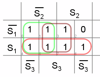
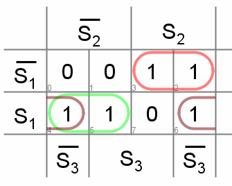
1
\$\begingroup\$

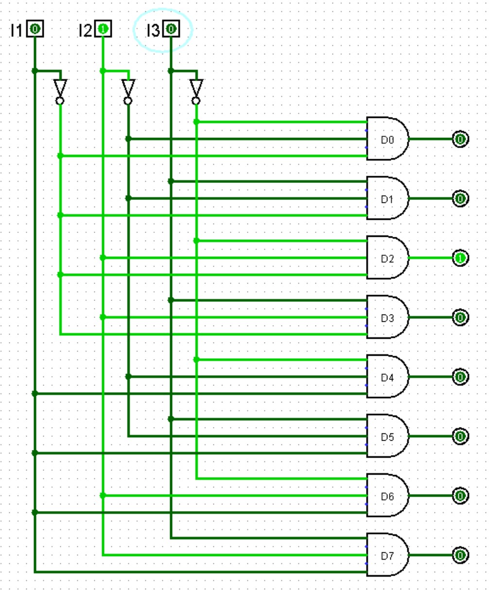
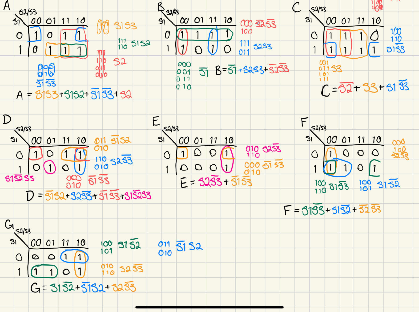
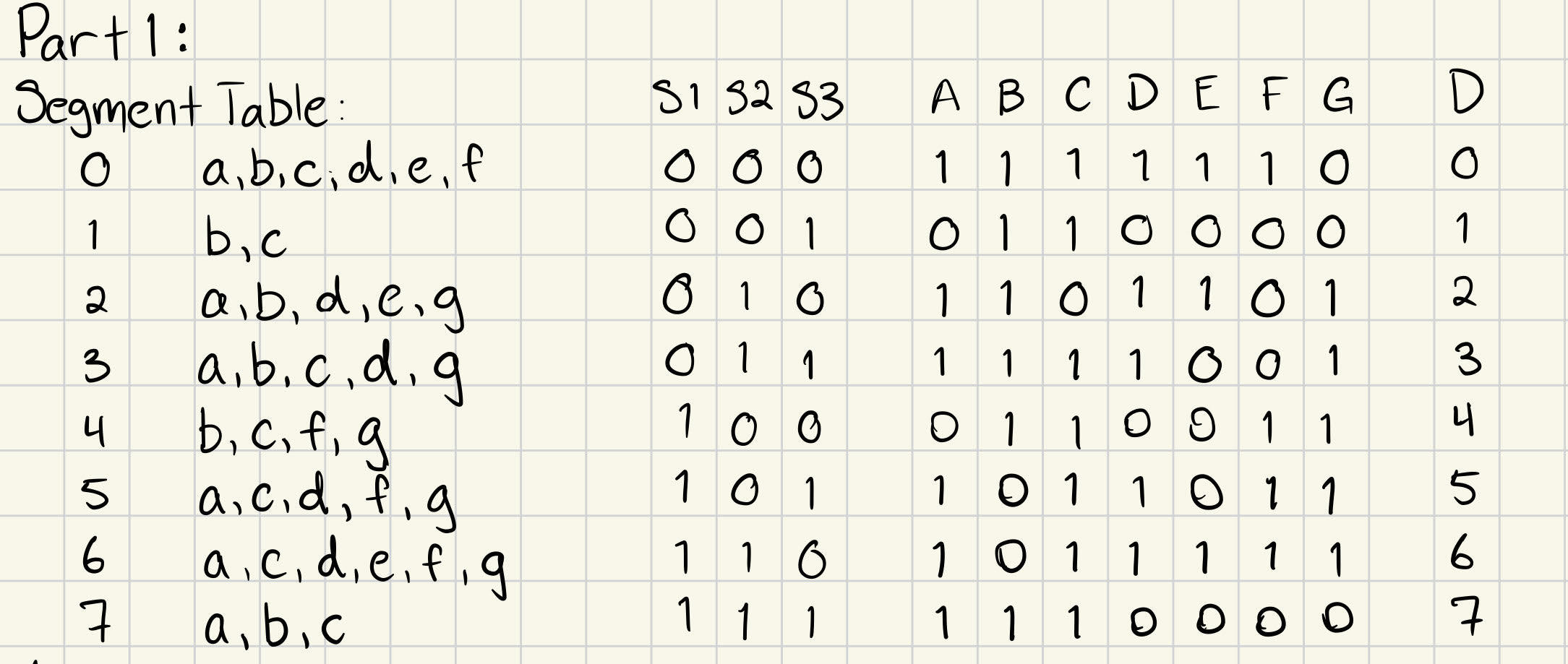
I believe I'm having some issues interpreting an assignment for my Digital Systems class. What I've done so far is make the segment table for the display, make a truth table for A-G, k-maps for A-G, Logisim diagram for a normal 3 to 8 for reference, and a Logisim diagram for the equations from the k-maps.

The assignment says that, for the 7-segment display, I need to "Implement the circuit only in Logisim/Circuitverse using a 3-8 decoder (built with AND gates and NOT gates), OR gates, and a 7-segment display driver." I've attached some screenshots of the work I've done so far for reference. I'm unsure if I need to take the normal 3 to 8 decoder and figure out a way to use a OR gates to output correctly to the 7-segment. Or do I need to derive the equations like I've done with the k-maps? Like a 7-segment decoder? Below is my work, the language of the assignment is what's really boggling me. Do you think that I've done it correctly already? I'm not looking for the answer to the question, but rather if I'm on the right track or not.

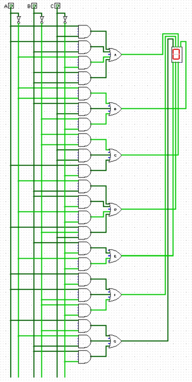
3 input 7-segment decoder

3 to 8 decoder

K-MAPS

segment table and truth table

\$\endgroup\$
2
  • \$\begingroup\$ A 7-seg decoder has 4 binary inputs to it, doesn't it? The assignment doesn't seem to be clear on this, though the 3-8 decoder is suggestive, so perhaps it was in a lecture or added material you don't show that this only needs 3 inputs? \$\endgroup\$ Commented Apr 26 at 2:21
  • \$\begingroup\$ Reading more closely, perhaps this problem is only to be a very special kind of 3-to-8 decoder built as an AND/OR system like might be found in a GAL16V8. In that case, I find this result. I specifically did NOT optimize this for gates. It's a straight-out GAL16V8 approach. \$\endgroup\$ Commented Apr 26 at 2:38

2 Answers 2

1
\$\begingroup\$

The circuit you made with the k-maps will work, but in the instructions it says to use a 3-8 decoder and OR gates. Whether or not your calculated solution will be valid for your assignment, is something you should ask your professor.

However, is also possible to drive a 7-segment using the 3-8 decoder and OR gates; if that is what you were wondering. I will not demonstrate how to here though, per your request of refraining from directly answering the question.

\$\endgroup\$
3
  • \$\begingroup\$ Ok, I may have shot myself in the foot a little bit putting the no answer bit. I've spent a good bit trying to figure things out but no luck thus far. Should I be connecting the OR gates back to the original inputs, A/B/C in some fashion? edit: Would this be considered a BCD to 7-segment decoder? \$\endgroup\$
    – Anthony L
    Commented Apr 25 at 23:41
  • \$\begingroup\$ The solution ended up being to connect each output to the appropriate OR gates, in this case segments A-G. I was way over thinking this \$\endgroup\$
    – Anthony L
    Commented Apr 26 at 21:15
  • \$\begingroup\$ Sorry for not getting back to you, I was out of town. Glad you were able to figure it out! \$\endgroup\$
    – MXVG
    Commented Apr 28 at 1:38
0
\$\begingroup\$

I did find a minimization error. See below.

some initial thoughts

A 7447 7-seg decoder uses 4 binary inputs, not 3. But I take it that this is to be only have 3 binary inputs and works only for 0 to 7. (No 8 or 9 is available.)

Also, I think I see in the problem statement that you aren't supposed to actually use a 3-to-8 decoder module, but instead you are supposed to build a 3-8 decoder out of AND and OR gates, with NOT allowed.

This leaves open a question in my mind. A natural assumption that experienced designers would make is that a 3-to-8 decoder is a very specific thing. But, technically, I could make a 3-to-8 decoder that produces A-to-G outputs for a 7-segment display and add an 8th output that is always '0' or always '1' and it would still be a decoder and more specifically it would be a 3-to-8 decoder in every possible meaning of the phrase. Just not the 3-to-8 decoder that one would normally think of when seeing the phrase. Still, I could make a very strong argument that this term allows my specific interpretation in this specific case.

So this leaves me not wanting to go down that rabbit hole and to instead drill in on your k-maps.

k-maps

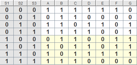
In looking over your k-maps, I believe I may have found an error. Here's the table I used:

enter image description here

The above matches your table. (Well, I copied it from your table so I hope so.)

Here's the error. It's C's table:

enter image description here

So, the logic here is \$C=S_1 + \overline{S_2} + S_3\$. That's the only error I found.

There is another note, though:

Here's another way to see G:

enter image description here

That's not better than what you did (which is correct.) It's just another way to see it done, in case it helps.

(I used Neemann's Digital software to produce the above table and k-maps.)

\$\endgroup\$

Your Answer

By clicking “Post Your Answer”, you agree to our terms of service and acknowledge you have read our privacy policy.

Not the answer you're looking for? Browse other questions tagged or ask your own question.