0
\$\begingroup\$

I am facing start-up issues during power on for the STM32L433.

When voltage comes from zero everything works fine. But, if I disconnect the power supply from the wall socket and its internal capacitors are not fully discharged and reconnect, the STM32 does not start. In this case the reset pin is inactive, not responding to a manual reset!

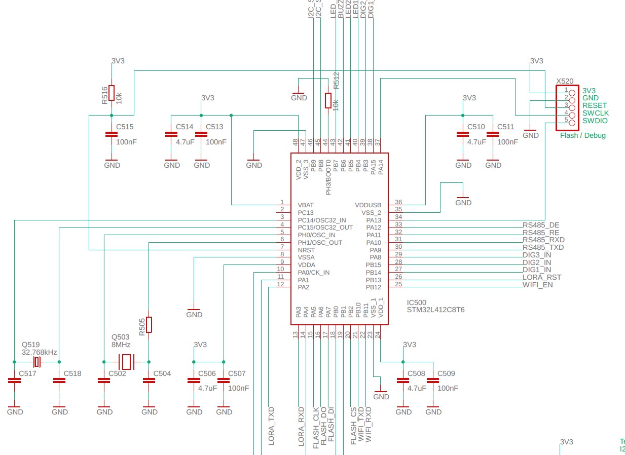
The board operates at 3.3 V. The reset pin has an external 39 kΩ pull resistor (also tested with 10 kΩ) and a 100 nF capacitor. Changing the BOR setting to level 4 seams to improve a bit. But, still not solving the problem.

There is a note about it in the documentation: Beware that for proper start-up, the supply voltage must drop to 0 V before it can be reconnected, otherwise proper power-on reset may not be guaranteed.

This situation might occur in the field, it is common to have a short time power fail. End the voltage will not drop to zero.

What can be done to improve the hardware or software to avoid this situation?
What's the reason to have an inactive reset pin?

Here is the link for the note mentioned above: https://community.st.com/t5/stm32-mcus/why-my-stm32-doesn-t-start/ta-p/49367#:~:text=Power%20supply,Vdd%20and%20Vdda%20supply%20pins
uController connections uController connections

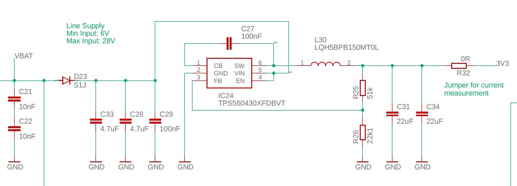
3V3 Voltage Regulator 3V3 Voltage Regulator

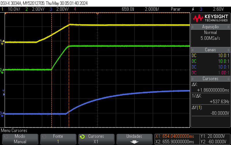
(1) 12V Supply input, (2) 3V3, (3) Reset line. The 3V3 supply rises in 1.8ms (1) 12V Supply input, (2) 3V3, (3) Reset line. The 3V3 supply rises in 1.8ms
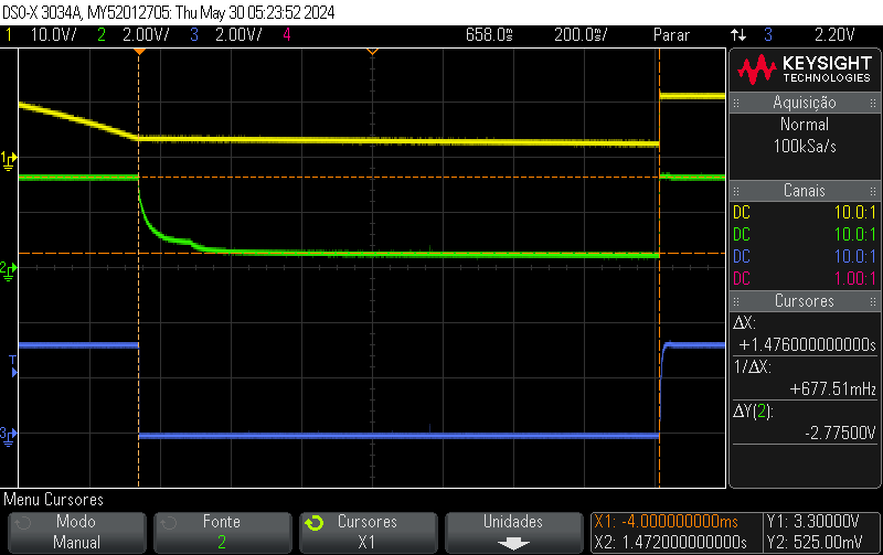
Switching off the 12V supply. After 1.5s the 3V3 line still with 500mV and this is enough to prevent the startup Switching off the 12V supply. After 1.5s the 3V3 line still with 500mV and this is enough to prevent the startup
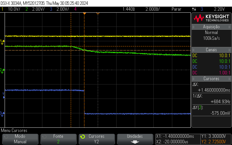
BOR configured at level 4, internal reset is triggered at around 2.7V BOR configured at level 4, internal reset is triggered at around 2.7V

\$\endgroup\$
9
  • \$\begingroup\$ Why do you even have a pull-up on reset? Which document from ST says you need it? Can you post the schematics? Is it a self-contained unit with no external connections? What power supply there is and how it is regulated to MCU? \$\endgroup\$
    – Justme
    Commented May 19 at 12:08
  • 1
    \$\begingroup\$ Is there a reason you are not using the regulator enable as UVLO, to turn regulator off when the 12V drops below some level of your liking? \$\endgroup\$
    – Justme
    Commented May 19 at 12:55
  • 1
    \$\begingroup\$ Maybe consequence of VBAT brownout erratum. Not sure about why NRST does not work. At any case, debug as usually, starting with finding out where PC is, potentially hot-connecting the debugger when the mcu is already in "frozen" state. \$\endgroup\$
    – wek
    Commented May 19 at 13:38
  • 1
    \$\begingroup\$ There are two errata for the L433xx related to brown-out in st.com/resource/en/errata_sheet/…. It doesn't look like your issue, but it might give you another vector for troubleshooting. \$\endgroup\$
    – MrGerber
    Commented May 19 at 14:50
  • 1
    \$\begingroup\$ @IGtti No, not saying to put a voltage monitor IC (it would also help). I am asking the regulator provides you a voltage monitor, why not use it? But also it is not clear what exactly keeps the voltage high. Best to scope the 12V and the 3.3V lines and be sure. If the MCU hangs due to low voltage vs speed, it might not be low enough for undervoltage reset. These things happen when voltages rise up and fall down slowly, or don't go low enough. \$\endgroup\$
    – Justme
    Commented May 19 at 15:34

2 Answers 2

0
\$\begingroup\$

The same link as you posted, clearly states:

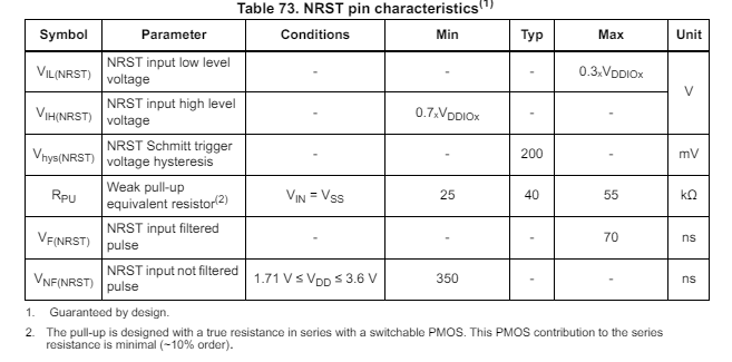
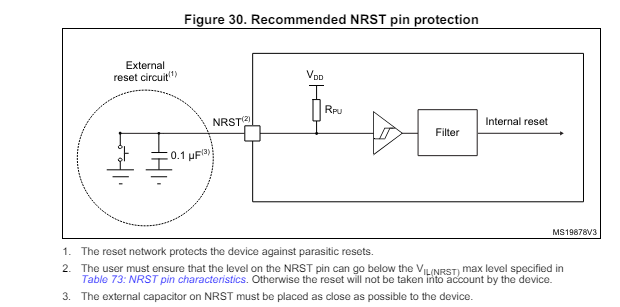
The NRST pin doesn't need to be driven externally. The only component needed is a 100 nF capacitor connected between NRST and Vss. Bigger capacitor, external pull-up resistor or push-pull device will cause overload of the internal MOS or possibility to miss the reset pulse.

EDIT: To clarfiy; The STM32 model in question has an internal pullup of typ 40k, so at best it is not necessary. If we take the information from OPs link in good faith - at worst it is detrimental. If we assume it's not correct, I don't think there is reason to put much faith in the rest of the information either. The datasheet and reference manual for STM32L4, and the ST App note AN4555 - Getting started with STM32L4 Series and STM32L4+ series hardware development should be the prime reference material.

Snippet from p152-153 in DS11449 Rev 7 enter image description here enter image description here

\$\endgroup\$
7
  • 1
    \$\begingroup\$ While true that an external resistor is unnecessary, having a 10k resistor would hardly cause overload or miss the reset pulse. It might be only part of the problem, or not the problem at all. The problem could really be the supply voltage going too low but not completely away, so the MCU won't perform a power-on reset. \$\endgroup\$
    – Justme
    Commented May 19 at 12:28
  • \$\begingroup\$ The external resistor is normally needed for other uControllers... I just removed it from the board and no difference. It still needs to wait until the voltage drops otherwise no startup, and the Reset pin has no function when this situation happens. \$\endgroup\$
    – IGtti
    Commented May 19 at 12:32
  • \$\begingroup\$ @IGtti Depend on microcontroller. Some have internal pull-ups. Some require external pull-up. So one cannot really say it's needed for other MCUs. It must be checked from manual. But like I guessed, the resistor was not the problem. \$\endgroup\$
    – Justme
    Commented May 19 at 12:37
  • \$\begingroup\$ I just added both schematic blocks, uC and voltage regulator. I am using an external 12V power supply as input for my board, and it takes some time to drops the voltage to zero... this is exactly the problem. It is necessary to wait some 20s to discharge the 12V supply... \$\endgroup\$
    – IGtti
    Commented May 19 at 12:44
  • \$\begingroup\$ @Justme I agree, but since the reasoning from OP was more or less founded from that link, I just wanted to show that the link also explicitly states that the arrangement chosen could be detrimental to the reset functionality. The STM32 model in question has an internal pullup of typ 40k, so at best it is not necessary. If we take the link in good faith - at worst it is detrimental. If we assume it's not correct, I don't think there is reason to put much faith in the rest of the information either. The datasheet and reference manual for STM32L4, and the AN4555 document should be the prime ref. \$\endgroup\$
    – MrGerber
    Commented May 19 at 14:08
0
\$\begingroup\$

After switching of the 12V power supply the uController 3V3 voltage level starts to decrease and as soon as it is above ~300mV and the power supply is reconnected the uController does not start!

I implemented the controlled Enable in the 3V3 voltage regulator, setting it to 6.8V rising and 6.1V falling. It does not solve the problem. You get an earlier 3V3 shutdown, but after some seconds the voltage still above 300mV, preventing the startup.

For the moment the solution I could find is to add a load at the output of the 3V3 voltage regulator. A resistor between 1k to 2k helps to discharge the remaining voltage very fast. It will add around 3mA to the circuit, which is not a problem for equipments powered by the mains.

The most important is to make the circuit robust against very common short power outages.

\$\endgroup\$

Your Answer

By clicking “Post Your Answer”, you agree to our terms of service and acknowledge you have read our privacy policy.

Not the answer you're looking for? Browse other questions tagged or ask your own question.