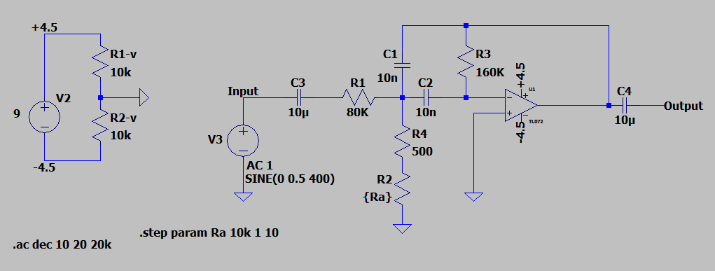
I want to build a Wah pedal following the tutorial linked. I am confused on why there are two voltage sources and why the one on the left does not connect back to the main circuit. The materials list only calls for one DC connector so wouldnt there only be one voltage source?
-
2\$\begingroup\$ NOTE: Circuit designs on "Instructables" often have problems. A critical error in the schematic is that there is no decoupling of the virtual GND. Add a 0.1 uF ceramic and 100 uF electrolytic capacitor in parallel across R1v and R2v. Without this, unwanted distortion is a real thing, as well as the circuit breaking into oscillation. \$\endgroup\$– AnalogKidCommented Jun 9 at 14:35
3 Answers
The labels "+4.5" and "-4.5" are node names. Any node with such a label is considered to be physically connected to any other node with the same label. Notice that those names also appear next to the op-amp. This means that those op-amp terminals are directly connected to source V2.
Source V2 seems to be a 9V battery (or your DC jack connecting to one); its positive connector is labelled "+4.5", and the negative connection is called "-4.5". They connect directly to the op-amp.
The same goes for the triangular ground symbol. All nodes with that symbol are physically connected together, forming one single node with lots of things connected to it. This "ground" symbol also tells the simulator which node is considered to have zero-volts potential, though this doesn't concern the builder, only people trying to understand or simulate it.
Source V3 is a test signal, for simulation, and doesn't form part of your final product. This will be replaced by another jack which will receive the input signal to be wahhed.
Note also that the output of this device will also be a jack with two connections. One of those will be the right end of C4, as labelled, but the other (the outer shielded part of the jack) will be connected to ground, together with all the other things with the triangular ground symbol.
The circuit on the left is simply a voltage divider to derive a virtual ground for the op-amp. Look at the 4.5 and -4.5v rails. While cheap to make, it will also waste power so long as a DC source is hooked up; so not friendly on battery life. Probably cause some distortion too.
-
1\$\begingroup\$ It's a wah pedal; it is supposed to add distortion. \$\endgroup\$– DereckCommented Jun 9 at 14:25
The voltage supply on the left is the DC power supply and it does connect to power pins of the op-amp.
The second voltage supply you see is a signal source to the circuit just like your guitar is. It is there so you can simulate the circuit what it outputs based on the input.
-
\$\begingroup\$ Thank you so much. So just to clarify the circuit on the left would connect to the opp amp and the V3 voltage source is just the output from the guitar? Not an actual battery. \$\endgroup\$ Commented Jun 9 at 14:56
-
\$\begingroup\$ Also I want to build this on a PCB board is there some software or soemthing that I can use to convert this schematic to a PCB layout so when I go to build itim not lost \$\endgroup\$ Commented Jun 9 at 15:03

