5
\$\begingroup\$

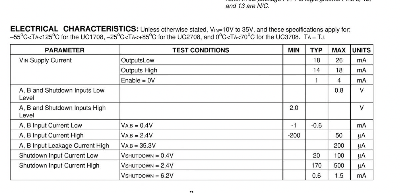
I'd like to drive a TI UC3708N gate driver from a handheld AWG square wave that varies between 0V and 2.5V. According to the data sheet, anything above 2V should be treated as high:

enter image description here

However, I'm not sure how much current the TI UC3708N gate driver is expecting. The data sheet is incomprehensible:

enter image description here

Clearly, it can't mean that the IC requires 50 A of input current to go high! Perhaps it's a typo and it means 50 mA? Even that seems too much.

I ask because I breadboarded a simple circuit, powered by 9V. When I manually connect the IC's Input to 9V, I get a high output. When I manually connect it to GND, I get a low output. Yet when I connect it to the AWG, I get a flat line.

I have two hypotheses as to the cause:

  1. The AWG's 2.5V is not enough to turn the IC on (despite the data sheet)
  2. The AWG can't source enough current to turn the IC on

I can solve the first with a simple common emitter amplifier, and the second with a common collector follower. But I'd first like to ask for help understanding what's actually required here.

\$\endgroup\$
4
  • 1
    \$\begingroup\$ FYI, the appropriate venue for such a question is the manufacturer's forums, a sales contact, or reporting a documentation error. There isn't much we can do here other than hint at what they possibly might've meant. \$\endgroup\$ Commented Jun 24 at 23:59
  • 2
    \$\begingroup\$ @TimWilliams I asked the question here because I wasn't sure if this was my misunderstanding. The general rule, at least in software, is blog.codinghorror.com/… not to blame the machine. \$\endgroup\$ Commented Jun 25 at 0:40
  • \$\begingroup\$ See also news.ycombinator.com/item?id=11090814 \$\endgroup\$ Commented Jun 25 at 0:40
  • 2
    \$\begingroup\$ Which part of the machine are we talking? Documentation is human-readable code of sorts; it's written by humans, and exactly as fallible as any software. In fact, worse: documentation doesn't ever need to work, users always have a chance to figure things out on their own. It's also safe to assume that "the machine" (corporations) are exactly as fallible as the people they're made of; especially today with rampant outsourcing and value-extraction by investors (not to get toooo political, but just to explain the general decline of infrastructure that's affected pretty much everything). \$\endgroup\$ Commented Jun 25 at 0:53

2 Answers 2

3
\$\begingroup\$

Yeah, I suspect that datasheet has typos, wouldn't be the first time. Leakage currents, and input currents of logic gates, are typically measured in pico or nano-amps, sometimes micro-amps. I suggest reporting this to the manufacturer via their website.

The reason your circuit is not responding as you expect is because the logic high input threshold is tyically 2.8V, and could be as high as 3.6V.

So your first hypothesis is most likely correct.

\$\endgroup\$
15
  • \$\begingroup\$ Doesn't the data sheet say 2V is enough for high? Am I misreading it, or is that in error too? \$\endgroup\$ Commented Jun 25 at 0:41
  • \$\begingroup\$ I was referring to the Enable input. Sorry, I can't post an image of it from my phone. \$\endgroup\$ Commented Jun 25 at 0:55
  • \$\begingroup\$ I have Enable tied directly to +9V. Only the Input AWG is limited to 2.5V. \$\endgroup\$ Commented Jun 25 at 1:00
  • \$\begingroup\$ The data provided for logic inputs A & B is not complete. Logic low max of 0.8V just means the threshold is always below 0.8V, but what is its min value that guarantees a LO? Could be anything. Same for Logic high, min= 2.0V, what is guaranteed hi level? The data for input current gives a clue: for HI is it given at 2.4V, not 2.0V. I suspect the actual threshold in your case will be between 2.5V and 3.0V; the timing diagram on page 5 shows the input is 0 to 4.3V. Thresholds might change with Vcc also, not sure. Suggest try some experiments to find out. Cheers. \$\endgroup\$ Commented Jun 25 at 4:50
  • 1
    \$\begingroup\$ Driving it with a stronger input solved it: electronics.stackexchange.com/questions/717475/… \$\endgroup\$ Commented Jun 25 at 20:26
13
\$\begingroup\$

This kind of nonsense is common as companies and their products are acquired and divested. Those parts were originally made by Unitrode. Below is a snippet from an archived Unitrode datasheet:

enter image description here

So the mu symbols got deleted due to some kind of font or similar issue. With mature products there is little pressure to fix the issue- existing users don’t care, most new users figure it out and years go by.. then the connection is forgotten.

\$\endgroup\$

Your Answer

By clicking “Post Your Answer”, you agree to our terms of service and acknowledge you have read our privacy policy.

Not the answer you're looking for? Browse other questions tagged or ask your own question.