1
\$\begingroup\$

I found this schematic on circuit digest.

I have tried to simulate it in LTspice.

enter image description here

That's the wave I got from the simulation. Most of time it's just DC and does not oscillate at all.

Is this going to work as an FM transmitter?

enter image description here

In real life, I want to use this BFQ19SH6327XTSA1 from Infineon instead of 2N22222. (link datasheet) ([download link for lib])5

***************************************************************
*   Infineon    Technologies    AG
*   GUMMEL-POON MODEL   IN  SPICE   2G6 SYNTAX
*   VALID   UP  TO  6   GHZ
*   >>> BFQ19S  <<<
*   (C) 2014    Infineon    Technologies    AG
*   Version 2.1 October 2014
***************************************************************
*.OPTION TNOM=25, GMIN= 1.00e-12
*BFQ19S C B E
.SUBCKT BFQ19S 11 22 33
*
CBEPAR 2 3 1.941E-014
CBCPAR 2 1 5.476E-013
CCEPAR 1 3 7.843E-013
LB    2 20 2.448E-009
LE   3 30 1.706E-009
Rci 1 10 0.002258
CBEPCK 20 30  8.568E-016
CBCPCK 10 20  1.201E-014
CCEPCK 10 30  8.448E-014
LBX    20 22 7.525E-013
LEX   30 33 1.178E-010
LCX   10 11  2.449E-010
*
*
Q1 1 2 3 M_BFQ19S
*
*
.MODEL  M_BFQ19S    NPN(
+   TNOM    =   25
+   IS  =   1.734E-015
+   BF  =   126.2
+   NF  =   0.9968
+   VAF =   52.15
+   IKF =   1.035
+   ISE =   7.715E-015
+   NE  =   1.81
+   BR  =   13.1
+   NR  =   0.9968
+   VAR =   3.079
+   IKR =   0.1214
+   ISC =   6.257E-015
+   NC  =   1.6
+   RB  =   5.552
+   IRB =   2.4E-005
+   RBM =   1.524
+   RE  =   0.2261
+   RC  =   1.814
+   XTB =   0.854
+   EG  =   1.11
+   XTI =   9.516
+   CJE =   4.551E-012
+   VJE =   0.7397
+   MJE =   0.3271
+   TF  =   2.467E-011
+   XTF =   4.69
+   VTF =   6.79
+   ITF =   1.027
+   PTF =   9.546E-017
+   CJC =   1.164E-012
+   VJC =   0.6791
+   MJC =   0.3983
+   XCJC    =   0.007944
+   TR  =   3.412E-008
+   CJS =   0
+   VJS =   0.3601
+   MJS =   0.02997
+   FC  =   0.567
+   KF  =   2.2E-14
+   AF  =   1.6)
***************************************************************
*
*
.ENDS BFQ19S
\$\endgroup\$
4
  • 2
    \$\begingroup\$ Do you trust the simulator and the peculiar result? If not, why simulate it? If I can't get a circuit to work in a simulator I won't use it. \$\endgroup\$
    – Andy aka
    Commented Jul 12 at 19:03
  • 2
    \$\begingroup\$ also, the quality of circuits from websites that offer a collection of circuits is usually bad. Like, really bad. Building a 100 MHz emitter on breadboard that you would want, as the text advertises, build in a classroom setting with frustratable students? Terrible idea, even if it works, it works because of parasitics that are not part of your schematic helping it work. If it doesn't work, you won't be able to explain why, unless the circuit doesn't even oscillate in simulation, in which case, the schematic simply is worthless. \$\endgroup\$ Commented Jul 12 at 19:39
  • \$\begingroup\$ @MarcusMüller I am trying to make a PCB based on the design. this is the simplest design I can find \$\endgroup\$
    – kile
    Commented Jul 12 at 20:18
  • 1
    \$\begingroup\$ Simple is a secondary aspect, working is an actual requirement. \$\endgroup\$ Commented Jul 12 at 20:19

2 Answers 2

1
\$\begingroup\$

Made with microcap v12.

Something like this could be "used" ... As pointed out by @Marcus Müller.
It requires some add-on on the resistor values specifically adding "parasitic" capacitors.
See my C4, C3, capacitors and C5, R3 resistor (~ antenna).
The resulting wave "could" be an FM oscillation depending on V2.

enter image description here

Added picture with BFQ19 (= BFR96 ? with some adjustments), modulated 100 kHz ...

.MODEL BFR96 NPN (LEVEL=1 AF=1 BF=9.80000E+001 BR=8.53970E+001 CJC=2.38386E-012

  • CJE=5.15057E-012 CJS=0 EG=1.11000E+000 FC=500m GAMMA=10p IKF=2.00000E+000
  • IKR=3.08736E-002 IRB=1.00000E-006 IS=2.44463E-015 ISC=3.07780E-015
  • ISE=3.95722E-014 ISS=0 ITF=2.48030E-001 KF=0 MJC=2.14438E-001
  • MJE=3.77782E-001 MJS=0 NC=1.12019E+000 NE=1.41333E+000 NF=9.87224E-001
  • NK=500m NR=9.78180E-001 NS=1 PTF=0 QCO=0 QUASIMOD=0 RB=3.00000E+000
  • RBM=3.00000E+000 RC=6.62000E-001 RCO=0 RE=7.17149E-002 TF=1.61902E-011 TR=0
  • TRB1=0 TRB2=0 TRC1=0 TRC2=0 TRE1=0 TRE2=0 TRM1=0 TRM2=0 VAF=2.66948E+001
  • VAR=4.69684E+000 VG=1.206 VJC=2.98165E-001 VJE=6.00000E-001 VJS=750m VO=10
  • VTF=2.83687E-002 XCJC=1 XTB=0 XTF=7.50000E+001 XTI=3.00000E+000) .ENDS

enter image description here

\$\endgroup\$
9
  • \$\begingroup\$ Antonio51 I can't see your picture. oh no, that request didn't look right RayID: 8a23ccf73fe98295 \$\endgroup\$
    – kile
    Commented Jul 12 at 20:31
  • \$\begingroup\$ @kile I don't understand ... RayID: 8a23ccf73fe98295 ? \$\endgroup\$
    – Antonio51
    Commented Jul 12 at 20:35
  • \$\begingroup\$ It just can open your picture. this is error id \$\endgroup\$
    – kile
    Commented Jul 12 at 20:38
  • \$\begingroup\$ What transistor did you use? Can you try this BFQ19SH6327XTSA1 from Infineon? \$\endgroup\$
    – kile
    Commented Jul 12 at 20:39
  • \$\begingroup\$ @kile 2N2222 ... I forgot to mention ... \$\endgroup\$
    – Antonio51
    Commented Jul 12 at 20:39
2
\$\begingroup\$

I would at least suggest a high-frequency ferrite bead or resistor in series with the base if using an RF transistor.

Using anything beyond MMBTH10 is overkill and inviting trouble, really. It's not a fancy circuit and it doesn't need or want much.

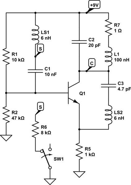
The simulation is missing parasitic layout elements. Consider the loop of three capacitors here:

schematic

simulate this circuit – Schematic created using CircuitLab

These values are very much straining CircuitLab's capability, but for sake of representation, it does work sometimes:

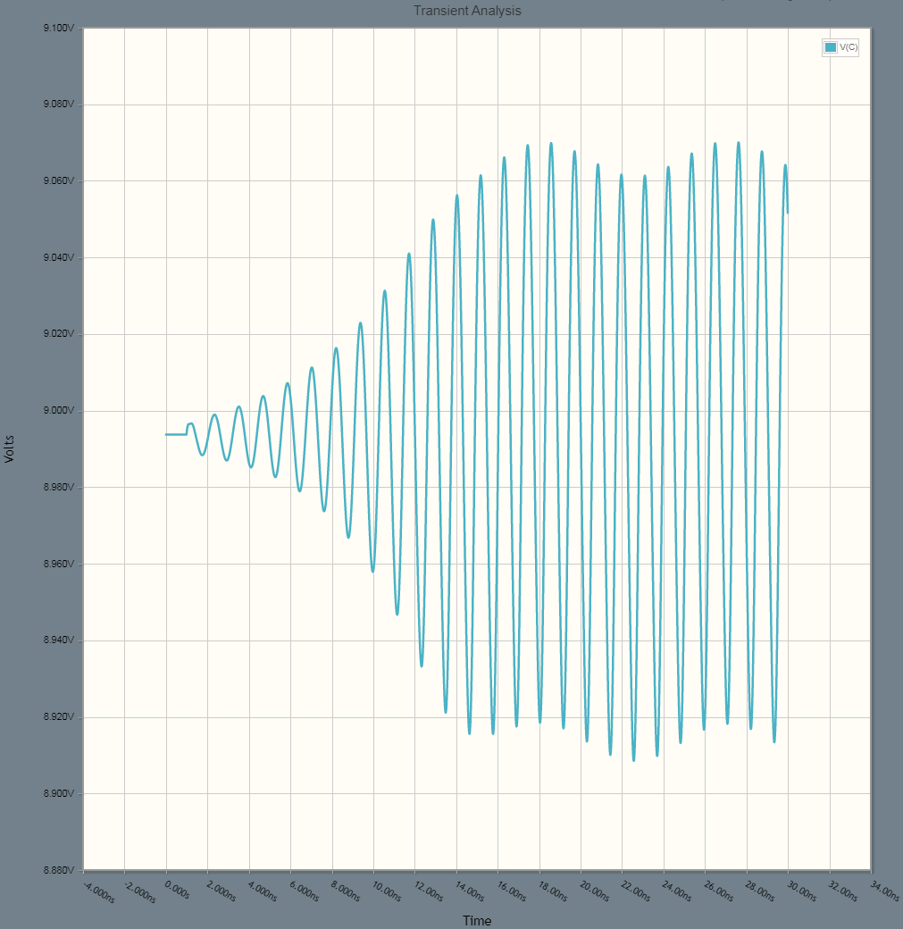
plot

That's about a 1GHz tone riding on (or perhaps dominating over?) the 100MHz mode. The key change is LS1/2 due to just a few mm of trace length between components, including their own lead and body length. Stray inductance accumulates in the ballpark of 0.5 nH/mm so it doesn't take much when you're talking GHz fT transistors.

The key pattern is the capacitors to all terminals of the BJT, making a low-impedance loop that inevitably has some inductance, and HF oscillation (as in, higher than intended) is perhaps inevitable.

Breaking that loop, by adding resistance to one or more pins, particularly resistance only dominant at such frequencies, is the usual strategy. A different topology can also be chosen that is less susceptible to such modes of oscillation.

Note that a ferrite bead acts as a parallel RLC, having low impedance at low frequencies, rising to some (resistive) peak at some mid frequency, then falling above there. When the peak is positioned over the HF oscillation frequency, the impact on the intended mode is small (the FB will still be lossy at 100MHz, but not as much, and more loop gain is available at lower frequencies, making the oscillator more tolerant of that loss) while the impact on HF mode is strong. To use an RF transistor here, consider a small chip FB rated 20-50Ω @ 100MHz, or preferably 50-200Ω somewhere in the 500-3000MHz range.

2N2222 and other general-purpose types are mostly too slow (internal resistance, capacitance, other time constants) to encounter such HF oscillation, hence the circuit is fairly safe to use with minor variations.

\$\endgroup\$
2
  • \$\begingroup\$ How are you gonna model parasitic layout elements? As transmission line? And I can't find any free plug-in that can extract parasitic layout elements in KiCad. \$\endgroup\$
    – kile
    Commented Jul 13 at 17:58
  • 2
    \$\begingroup\$ @kile Parasitics are approximated just as regular inductors and capacitors, use as many as necessary for the desired accuracy. But usually, the circuit is going to be tuned by trial and error anyway, so practical circuit designers don't really care about accurate parasitics modeling, which is difficult with many unknowns. Instead, roughly knowing they're "there" is sufficient (unless you're creating a reusable SPICE model for general use). In contrast, chip designers use parasitic extractions and field solvers extensively to model parasitics as best as they can, since tuning is not an option. \$\endgroup\$ Commented Jul 13 at 18:13

Your Answer

By clicking “Post Your Answer”, you agree to our terms of service and acknowledge you have read our privacy policy.

Not the answer you're looking for? Browse other questions tagged or ask your own question.