2
\$\begingroup\$

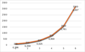
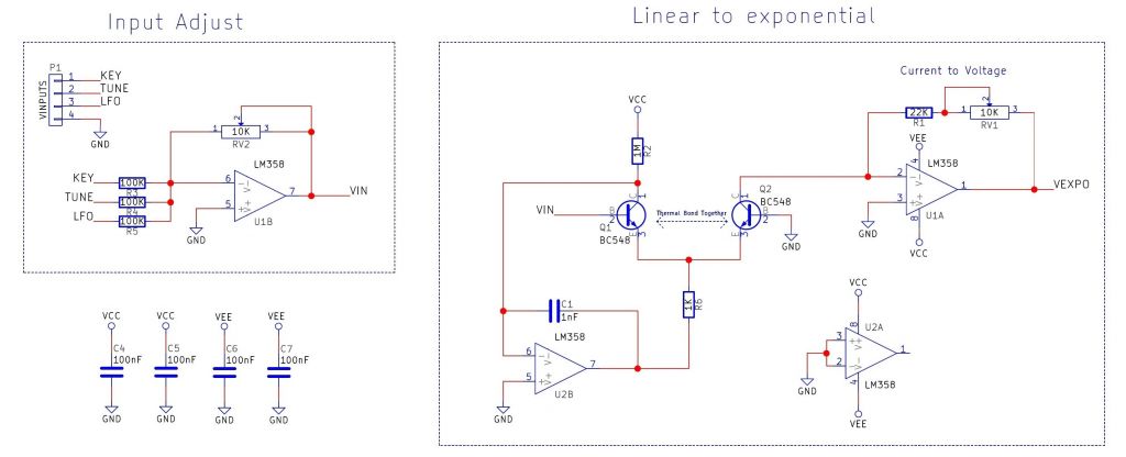
I'm making a VCO for use as a module in a synth. The oscillator part is working fine. I also need to translate a 1v/oct voltage input to a log scaled voltage output in order to get the correct freq out of the VCO. Makes sense. So I built a lin to log circuit as well (2 opamps tied together with emitter), which also works fine. enter image description here
I did some testing with my signalgen and fed the VCO to see what voltage is needed for certain freqs.

enter image description here

enter image description here

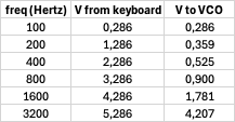
In the column V from keyboard is the ideal voltage coming from my keyboard (which in reality gives a 0-5v output). The column V to VCO is the actual voltage needed (as tested with my signalgen) resulting in the correct freqs.

The 2 combined though (OSC and LIN2LOG circuit) dont match up (surprise surprise. I dont want it to be correct over the whole musical range; a normal expected behaviour for a VCO would be 2-3 octave of correct sounding octaves and a pitch knob to set the base freq. Im totally ok with that.

My assumptions: lin to log conversion is what it is. I cannot control the slope (because of the behaviour of the transistors) so I have to focus on the input of things. My idea is to 'scale' the input in such a way that the output curve of the LIN2LOG circuit behaves like my graph.

My question is the following: Am I on the right track here? What is the best place to start looking for the solution? Trying to learn here :-)

\$\endgroup\$
1
  • \$\begingroup\$ I don't see the conversion factor needed between the VCO voltage and the LIN2LOG voltage. \$\endgroup\$ Commented Nov 2 at 16:41

1 Answer 1

3
\$\begingroup\$

You are mostly on the right track.

The log() circuit will generate an output exponentially dependent on VIN/26mV. Thus for each 26 mV increase in VIN, the output signal will change by a factor of e (2.718). Equivalently, each 18 mV increase in VIN will double the output (e.g. 1 octave), and a 60 mV increase will increase the output 10x.

Your VCO is not particularly linear (V to F is not linear). It is not clear what different transfer function you need.

You might find that using a small MCU (Arduino) with an ADC and DAC is the easiest way to implement any transfer function you want.

\$\endgroup\$
3
  • \$\begingroup\$ Where does VIN/26mV come from? Is that number based on the numbers I supplied or is it a given 'fact' because I use transistors and thats just part of their behaviour? \$\endgroup\$ Commented Nov 2 at 22:40
  • 1
    \$\begingroup\$ It's fundamental to the operation of BJTs (at room temperature). The collector current is ISexp(qVBE/kT - 1). kT/q is 26 mV at room temperature. IS will vary device to device, but the rest of the equation is fairly inviolable. \$\endgroup\$
    – jp314
    Commented Nov 3 at 1:58
  • \$\begingroup\$ @jp314 - And the exponential dependence on temperature gives some insight into why monolithic differential amps, where two transistors are physically adjacent on a chip, has had a very large impact on analog circuit design. Adjacent transistors on a chip are far better matched, both thermally and in terma of gain, than is possible for discrete parts. \$\endgroup\$ Commented Nov 3 at 4:13

Your Answer

By clicking “Post Your Answer”, you agree to our terms of service and acknowledge you have read our privacy policy.

Not the answer you're looking for? Browse other questions tagged or ask your own question.